Audio Features User Manual
Audio Features - User Manual and Reference
Audio Features
User Manual and Reference
|
DATE |
07/10/2020 |
|
PRINCIPAL AUTHOR |
P Eszlari |
|
SECONDARY AUTHORS |
|
|
VERSION |
V 1.0; 1.2 |
|
UPDATE |
Updated from 4.4 (25/07/2014) |
|
MISC |
Docs style applied Dec 2020 |
Overview
This document explores the audio capabilities of Tog and explains how to use all audio features. It is written based on the assumption that the reader is already familiar with Tog, particularly with Nodes, Timeline editor, Animators, video input, opening video files, using Shaders and Textures.
Introduction
Tog handles audio signals gathered from several different sources. These comprise embedded audio in video streams passing through Tog from the video inputs, audio streams passing through Tog from the dedicated AES/EBU audio inputs, embedded audio streams in video files opened in a project and sound samples that are added to scripts as design elements by the user.
These are all synchronized in time with the running video frames from the point when Tog is launched. Sound samples can be opened and processed in a script by using the Audio Node dedicated for this purpose.Opening sound files, start and stop play back, processing volume and mute can all be controlled by animators and other input methods, in sync with video frames.
Audio controls for video files are also accessible in the Shader Node when a video file is opened as an image.The current audio processing state such as channel routing, volume levels and mute can all be saved in the script by using Audio Nodes and Shader Nodes.
The audio streams from 64 inputs are distributed through 16 output channels that can share multiple sources by mixing streams.These can share outputs with streams passed through from the inputs or other Shader and Audio Nodes. In the following article these features will all be explained in detail.
Audio features in brief
- Playing back any number of audio “wave” format files with mono or stereo channels
- Playing back video files with mono, stereo or Dolby 5.1 PCM sound
- Input audio from other equipment through digital AES/EBU inputs on 16 audio channels
- Play back audio from SDI video input streams on 64 audio channels
- Process all audio, route to output channels and mix
- Automate audio processing such as volume levels and mute, in sync with video frames using animators or other input methods
- Output audio on 16 individual channels both as AES/EBU and AIV
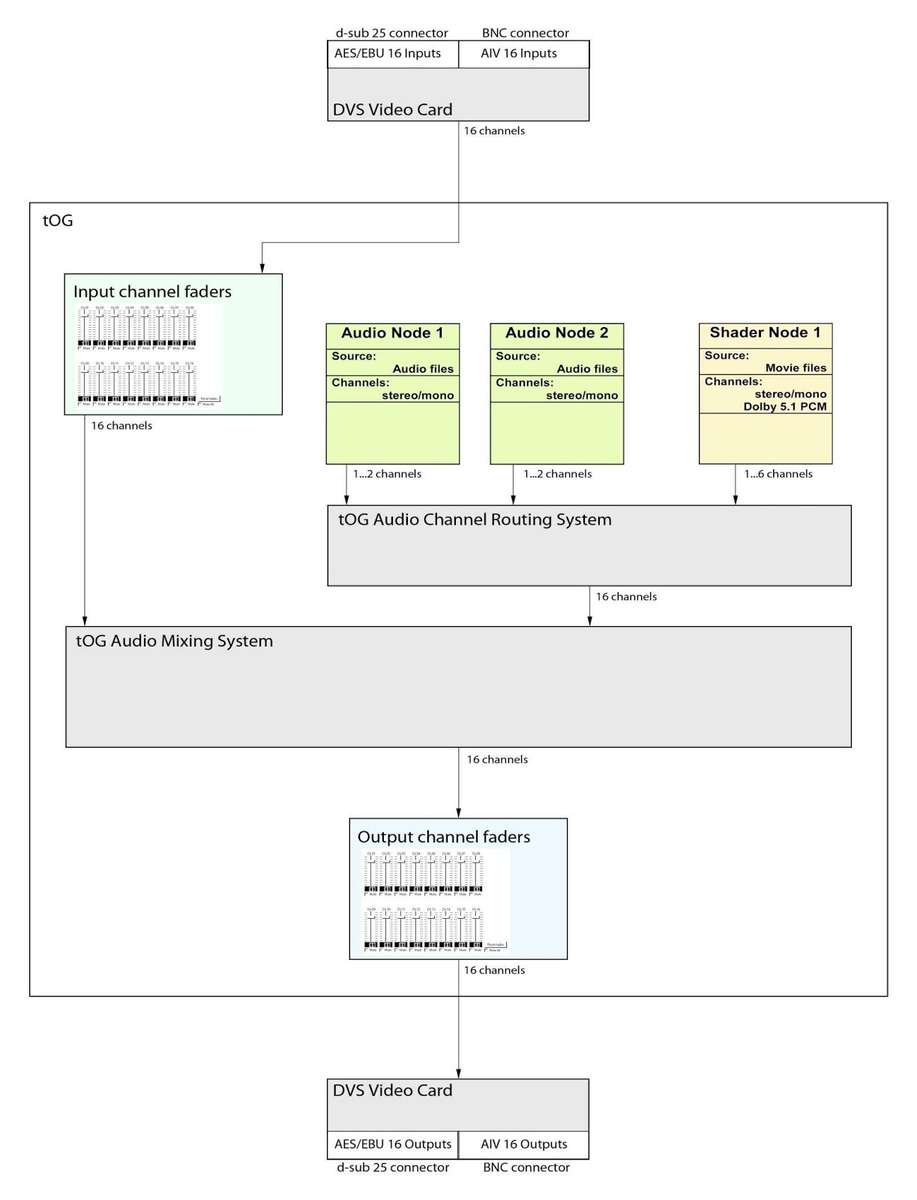
Audio Signal Path
Hardware
Tog uses the audio interface of the installed video I/O boards to handle audio streams. This includes getting audio signals into the computer and into Tog from external sources and to output all audio signals after processing. 16 mono audio streams are carried on each video SDI inputs and outputs.
Video board compatibility
DVS Atomix and Centaurus II boards
32 channel input on 2 SDI video and 16 channel output on one SDI. 16 channel I/O on AES/EBU via d-sub 25 pin on extension panels.
NVIDIA SDI Capture and SDI Output boards
64 channel input on 4 SDI video and 16 channel output on one SDI. These cards work in connection with the NVIDIA GPU card, such as the Quadro 5000 or k5000.
Connections
- AIV: the audio signal is embedded in the video stream that is connected to one of the SDI inputs on the video board. The audio output channels appear on the SDI output sockets (BNC type).
- AES/EBU: (DVS only) standard AES/EBU d-sub 25 pin connector (Tascam pin layout). Accessible by connecting two separate audio panels to the DVS board. Each audio panel with one connector provides 8 inputs and 8 outputs (channels 1-8 and 9-16).
NOTE: Refer to the Audio Preferences section of this document on how to change the audio settings and how to access the input and output controls.
See the Audio Hardware Setup section for more details on the DVS board audio hardware settings and connections, and the audio panels.
Input section
There are four audio input sources that Tog handles: two external and two internal sources.
External sources:
There are two ways to input audio into Tog and they cannot be used simultaneously:
AIV (Audio embedded In Video):
The audio signal is embedded in the video stream that is connected to the SDI inputs on the video input board. 16 mono audio channels can be carried this way. How many of these are used depends on how the audio information is embedded in the carried video stream. Typically a mono stream uses two channels instead of one with the two being identical.
- NVIDIA Capture boards: 64 channels on 4 SDI video streams.
- DVS Atomix boards: 32 channels on 2 SDI video streams.
AES/EBU:
This is available only on the DVS board. This is the dedicated audio input on Tog that can be used in connection with any equipment that has AES/EBU audio outputs.
This provides 16 channels on 2 extension audio panels.
NOTE: All of the unused input channels can be switched to mute to avoid any unwanted signals or low level noise, to enter into the signal path. This is important because even a very low level noise can cause digital clipping (distortion) on the outputs when mixed with other high level audio signal.
Internal sources:
Internal audio sources are audio and video files that are opened in Tog. They are accessible by using nodes.
- Audio files are opened and played back through the Audio Node. See the Audio Node section below.
- Video files are opened and played back as an “image” through the Shader Node. See the Audio in video image – Shader Node section below.
Output section
Tog outputs 16 mono channels of audio on SDI video outputs, and on DVS boards also as AES/EBU simultaneously. The output channel controls can be accessed in the Preferences window under the Audio tab.
Audio preferences
Audio Tab
The Audio tab in the Preferences editor allows the user to access the audio settings and to control audio input and output levels.
NOTE: These settings do not require Tog to be re-started
Enable Audio I/O
When deselected, all audio functions are bypassed.
Settings
DVS input source
- AIV Embedded
- This radio button is to select the input SDI video stream with embedded audio, as external input source.
- AES/EBU
- Select the AES/EBU inputs of the DVS board as external input source.
NOTE: On DVS boards Tog outputs all 16 channels of audio both as AIV embedded and as AES/EBU simultaneously, regardless of these settings.
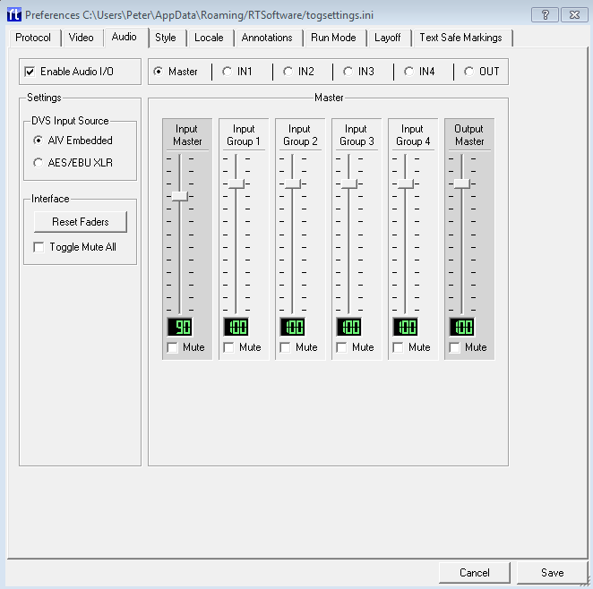
Master page
The Master page shows six control channel strips. These are independent from the individual channel controls and placed sequentially in the signal chain.
- Input Master
- This allows control over all the inputs (64) at once.
- Input Group 1-4
- These each control 16 channels at once for each video input.
- Output Master
- This allows control over all the outputs (16) at once.
Each channel has a volume fader, a mute button and a digital display showing the fader levels.
The faders are scaled from 0 – 120, 100 being the default value at which setting the volume is not changed. Values 0 – 99 mean attenuation and 101 – 120 mean amplification. The value 0 results in silence.
Input and Output pages
Sharing the same layout, each page has controls for 16 individual channels. Each channel has a volume fader, a mute button and a digital display showing the fader levels.
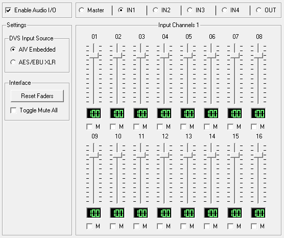
IN1, IN2, IN3, IN4 pages:
These correspond to the 4 SDI video inputs on the NVIDIA capture board, or IN1-2 on the DVS board.
OUT page
This allows access to the 16 audio output channels on the DVS or NVIDIA boards.
These controls are the last before the audio streams are routed to the physical outputs on the video board. They control the 16 mono channels separately regardless, whether their source is mono, or part of a stereo or surround source.
NOTE: it is possible to overload the audio signal path, which causes distortion in the signal. Make sure you adjust the input, output and local volume levels correctly, especially if you share output channels between several audio sources. For more information see the Mixing audio section of this document.
Interface
- Reset faders
- This button is to re-set all faders to default (100)
- Toggle Mute all
- This checkbox is to mute / un-mute all channels at once
Save
Click on this to save audio settings. If the audio settings have been changed since the preferences window was opened a window pops up with three options:
- Save changes: The audio settings are saved to disk and will be re-loaded when Tog starts next time.
- Use changes: Keep the changes for now but do not save them. (Same as the Esc key or closingthe preferences window).
- Undo changes: Revert to the settings that were before the preferences window was opened.
Cancel
Revert to the settings that were before the preferences window was opened.
Audio Node
The Audio Node allows the user to open and play back audio files in sync with the events of the graphic scripts.
Audio file format requirements
|
File format |
wave (PCM), .wav extension (e.g.: somesound.wav) |
|
Channels |
mono or stereo (i.e. 1 or 2 channels) |
|
Bit depth |
16, 24 or 32 bit |
|
Sample rate |
48000 Hz (48 KHz) |
Interface
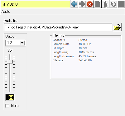
Audio file
File chooser.See the compatible file formats above.
Output
Select output channel
- For mono audio files the channels are selected as one channel for each Audio Node.
- For stereo sources the output channels are selected as channel pairs, i.e.: two channels for each Audio Node. Each channel is paired with the next channel.
- (1-2, 3-4, 5-6…)
There is no limitation on how many Audio Nodes share the same output channels. Refer to the Mixing audio section of this document on how to work with several different audio signal paths in Tog.
Vol
Local volume fader for this audio source. When sharing output channels between several sources the volume levels must be set carefully for each source to avoid overloading the signal path.
Mute
Mute or un-mute this Audio Node.
File info
Audio file details are printed here.
Channels
Stereo / mono
Sample rate
Sampling frequency
Bit depth
Bit resolution
Length (Ms)
The length of the file in milliseconds.
Length (frames)
The length of the file in video frames.
File size
Size of the opened file in Kbytes
Usage
- Place an Audio Node under an object anywhere into the scene.
- After selecting the Audio Node in the scene graph open an audio file using the file chooser in the audio editor window.
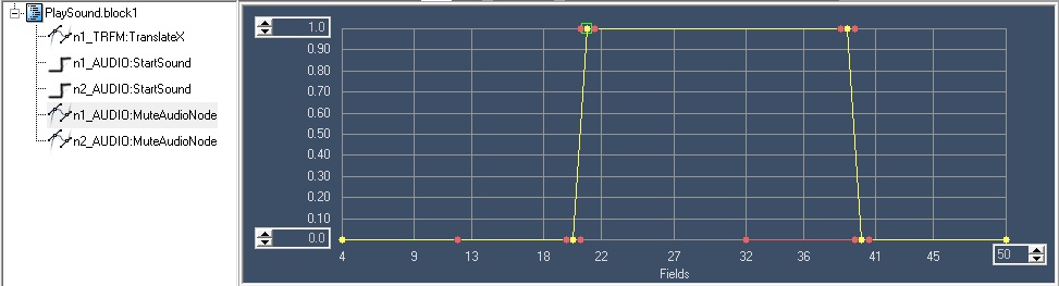
- Drag and drop the Audio Node from the scene graph to the timeline and set the StartSound AField as a step animator.
NOTE: For further information on how to use the timeline editor, refer to the Timelinesection of the Design and Edit document.
Audio options
Timeline editor
Crop beginning
The Field value in the Step Animator for the Audio Node represents the start of playback of the sound in seconds relative to the beginning of the audio file. By this method the user can virtually crop the beginning of a sound.
e.g.: if the Field value is set to 0.5 the audio playback will start half a second into the audio file when the step animator is hit on the timeline.
Crop end
The user can virtually crop the end of the animated sound by setting up a StopSound field as a step animator by dragging the same Audio Node from the scene graph to the timeline.
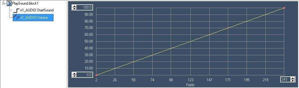
Volume animation
It is the best to use path animators to animate audio volume changes in Tog. The possible values set here by the path correspond to the valuesset by the volume faders: 0 – 120. (See below)
Volume levels can be animated for all the 16 inputs, outputs and any Audio Nodes by using the corresponding AField property.
NOTE: the resolution of the path animator is “1 value/video field”, however the volume changes gradually for each audio sample by automatically calculating the values between the beginning and the end of a field. The volume fader has a logarithmic response curve but the values that the animator path shows represent the movement of the volume fader. Therefore a linearly increasing path will result in a logarithmic volume change.
Mute animation
The easiest way to animate the mute and un-mute functions is to use path animators.
Mute source
Set the value to 1 or bigger
Un-mute source
Set the value to smaller than 1
The mute function can be animated for all the 16 inputs, outputs and any Audio Nodes (Figure 1.1).
Save Audio Node settings
The output channel, volume and mute settings for the Audio Node are saved in the current graphic script (.rb).
Audio in video image
Shader Node
The Shader Node allows the user to open and play back video files with mono, stereo and Dolby 5.1 PCM audio channels.
Usage
- Select a Shader Node on the scene graph
- Select a shader or create new
- Select the shader editor as the editor
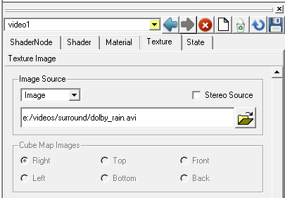
- In the Texture tab select Texture Image and set Image as Image Source
- With the file browser select a video file saved on your system
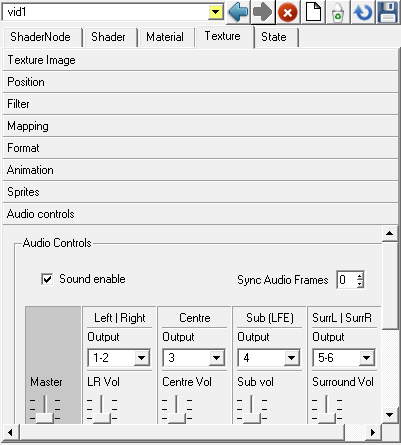
- In the Texture tab open up the Audio controls page to access the audio settings.
For more information on how to open and view video files using the Shader Node refer to the Shader Editor section of the Design and Edit documentation.
Audio controls for video
The audio controls here work much like in the Audio Node except that we can control multiple channels depending on the audio content of the video file. The controllers are also enabled or disabled depending on the audio content.
Sound enable
This checkbox is to enable / disable sound playback from this video file. When re-enable this option it might take a few seconds for the sound to re-sync with video frames.
Sync Audio Frames
Shifts the audio by frames relative to the video frames. This is a number scaled from (-10)-10.
Various video file formats may need some adjustment to get the audio in sync with the video frames.
Channel strips
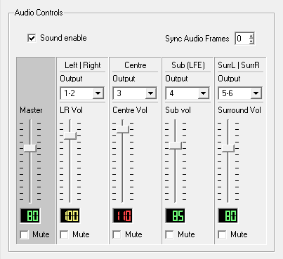
There are five set of controls:
- Master to adjust the four streams at once
- Left | Right: for stereo or mono sound
- Centre: for the Centre channel in Dolby 5.1
- Sub (LFE): for the Sub channel (a.k.a LFE) in Dolby 5.1
- SurrL | SurrR: for the Rear Left and Rear Right channels in Dolby 5.1
For each set of controls there is a channel router, a volume fader and a mute check-box.
Six channels are managed in two pairs and two mono channels on the 16 outputs:
Left–Right and Surround Left-Surround Right are always paired, therefore there are only four output channel routers for the six channels.
Save audio control settings
The output channel, volume and mute settings for the video are saved in the current graphic (.rb) script together with other Shader Node parameters.
- The Sound enable state is saved in the texture file when we save the shader.
Mixing audio
All audio streams can be mixed with one another in Tog, i.e. the 16 audio outputs can be shared between several audio sources. This is done by selecting the desired output channels for the source and then setting the balance between them by their local volume faders. When several sources share the same outputs they also share the corresponding output channel volume faders in the preferences editor that control their volume all at once.
Routing options
The audio inputs are “hardwired” to the correspondingly numbered output channels therefore they cannot be set by the user:
|
Input 1 |
Output 1 |
|
|
Input 2 |
Output 2 |
|
|
~ |
~ |
~ |
|
Input 16 |
Output 16 |
The volume level, however, can be set for each input by the input volume faders in the Preferences window under the Audio tab.
- Both the Audio Node and the Shader Node can be routed to any of the 16 outputs. Also each output can be shared between any numbers of sources.
- A stereo source always uses two outputs and a mono source uses one or two when the two being identical.
- The volume levels can be set by the local volume faders found at each audio source. When sharing outputs between several audio signals it is crucial to set all the signal levels carefully to avoid digital clipping.
E.g.: Suppose you use two audio files on two Audio Nodes. Their peak levels are on the maximum possible level before clipping occurs (0dB). If they share output channels their fader levels have to be set to approximately 80 to avoid clipping. This means an approximate 6 dB attenuation for each. Alternatively, reducing the output level with the clipping channel’s output fader will solve the problem as well.
Audio Hardware Setup
This section provides details about the audio hardware requirements for Tog and explains the available connections and settings.
Tog uses the audio interface of the DVS Atomix or DVS Centaurus II video boards. As the audio connections and settings are the same on the two boards we only detail the more recent Atomix board.
Overview
Atomix LT provides up to 16 channels digital audio (AES/EBU). With this up to two panels for audio can be delivered with the Atomix LT:
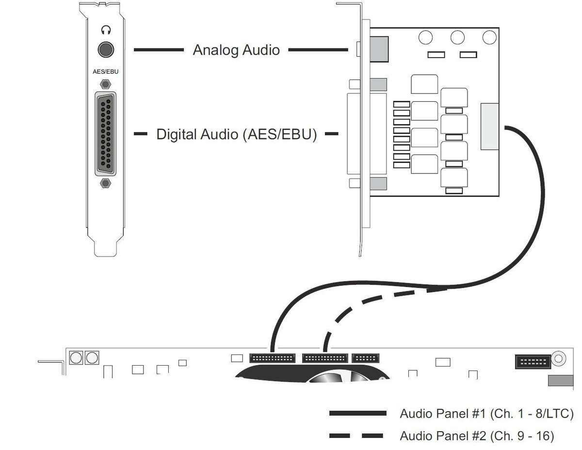
- One that has to be connected to the AUDIO 1-8/LTC connector on the Atomix LT board (in this guide referred to as ’audio panel #1’).
- One that has to be connected to the AUDIO 9-16 connector on the Atomix LT board (referred to as ’audio panel #2’).
There are two types of panels for audio available:
- One with analog and digital audio connections (called ’audio panel’, see section “Audio Panel”).
- One with digital audio plus RS-422 connection (called ’audio and RS-422 panel, see section “Audio and RS-422 Panel”)
The following tables show the possible combinations of the two types of panels and their recommended installations:
|
Delivered Panels |
Install as |
|
1 x audio panel |
audio panel #1 (AUDIO 1-8/LTC) |
|
1 x audio panel |
audio panel #1 (AUDIO 9-16) |
|
Delivered Panels |
Install as |
|
1 x audio panel |
audio panel #1 (AUDIO 1-8/LTC) |
|
1 x audio panel and RS 422 panel |
audio panel #1 (AUDIO 9-16) |
When only one panel for audio has been delivered to you, it should always be set up as audio panel #1 (i.e. connected to AUDIO 1-8/LTC).
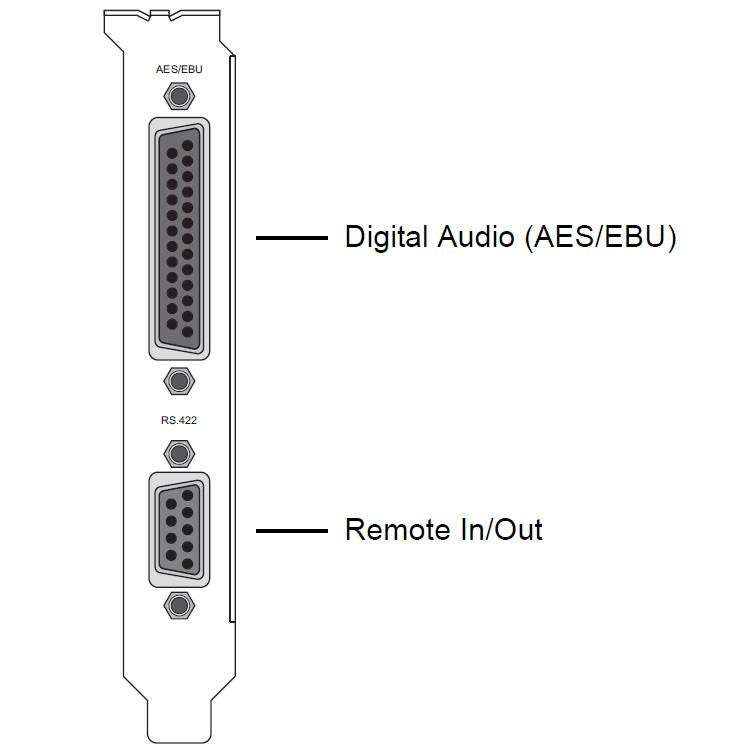
Audio and RS-422 Panel
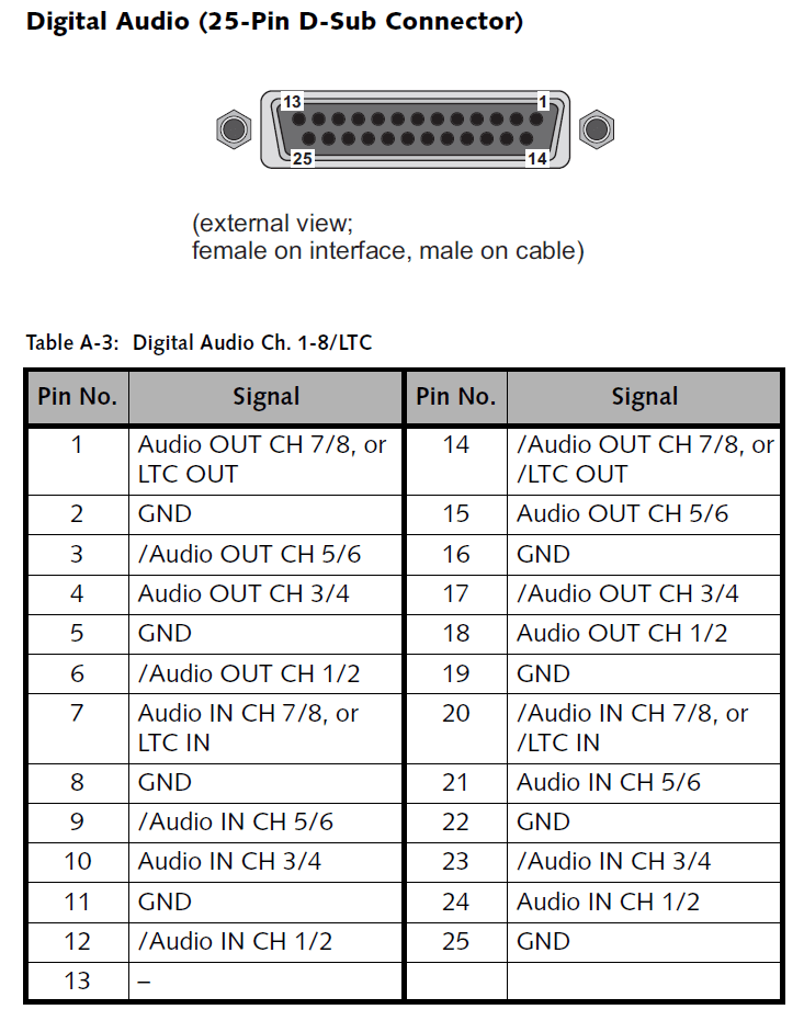
The audio and RS-422 panel provides a DB-25 connector for digital audio (AES/EBU) and LTC signals as well as a DB-9 connector for a standard RS-422 connection for remote control. (Figure 2.1) To the DB-25 connector you can connect a breakout cable providing eight XLR connectors to interface directly with audio devices. The pin-out of the RS-422 port can be can be switched between master and slave mode in the software. Pin-outs of the DB-9 and DB-25 connectors can be found in section “Signal In- and Outputs”.
|
Item |
Description |
|
Digital Audio (AES/EBU) |
DB-25 connector (female) for audio and LTC in- and output; provides either four stereo channels digital audio (channels 1 to 8) or three channels audio plus LTC; alternatively it can be used to provide the digital audio channels 9 to 16 |
|
Remote In/Out |
DB-9 connector (female), serial RS-422 interface for master or slave control |
NOTE: In a setup that contains this panel as well as one of the audio panels described in section “Audio Panel”, it is recommended to install it as audio panel
#2 (see section “Overview”). Prior to the installation of the panel you have to set/check the jumpers on the printed circuit boards for the appropriate settings (see section “Jumper Settings of the Audio and RS-422 Panel”).
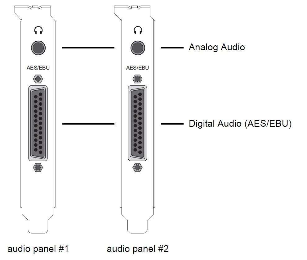
Audio Panel
Up to two audio panels can be included in your Atomix LT delivery (see section “Overview”). They provide each a DB-25 connector for digital audio (AES/EBU). One of the panels provides also an analog stereo headphone output and can be configured to transmit LTC signals. To the DB-25 connectors you can connect breakout cables providing each eight XLR connectors to interface directly with audio devices. Pin-outs of the DB-25 connectors can be found in section “Signal In- and Outputs”. (figure 2.2)
|
Audio Panel # |
Item |
Description |
|
#1 |
Analog Audio |
3.5 mm unbalanced stereo headphone jack to monitor the audio output |
|
Digital Audio (AES/EBU) |
DB-25 connector (female) for audio sig-nal and LTC in- and output; provides ei-ther four stereo channels digital audio (channels 1 to 8) or three channels audio plus LTC |
|
|
#2 |
Analog Audio |
Without function |
|
Digital Audio (AES/EBU) |
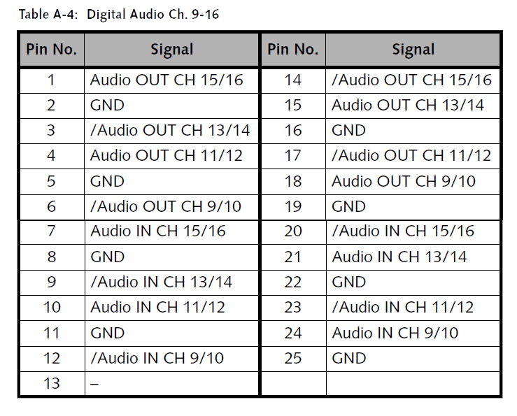
DB-25 connector (female) for audio sig-nal In- and output; provides the digital audio channels 9 to 16 |
NOTE: Prior to the installation of the panels you have to set/check the jumpers on their printed circuit boards for the appropriate settings (see section “Jumper Settings of the Audio Panel(s)”).
Jumper Settings of the Audio and RS-422 Panel
When installing the audio and RS-422 panel as the audio panel #1 (see section “Overview”), up to four stereo channels of AES/EBU or three stereo channels of AES/EBU and one LTC in- and output can be transmitted. This signal configuration has to be configured via jumper settings on one of the printed circuit boards mounted to the audio and RS-422 slot panel. Before installing the audio and RS-422 panel please check whether the jumpers on the printed circuit boards are set to your desired configuration and, if appropriate, adjust them (figure 3.1):
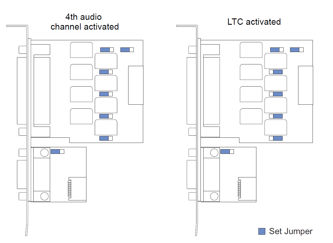
NOTE: In a setup that contains this panel as well as one of the audio panels described in section “Audio Panel”, it is recommended to install it as audio panel
#2 (see section “Overview”). Then the jumpers should be set as the indicated in the left drawing (figure above, 4th audio channel activated). After checking and, if appropriate, adjusting the jumpers you can continue the installation by checking the jumpers of the audio panels (if available).
Jumper Settings of the Audio Panel(s)
On the audio panel that should be installed as the audio panel #1 (see section “Overview”) up to four stereo channels of AES/EBU or three stereo channels of AES/EBU and one LTC in- and output can be transmitted. This signal configuration has to be configured via jumper settings on the printed circuit board mounted to the audio slot panel. Before installing the audio panel #1 please check whether the jumpers on the printed circuit board are set to your desired configuration and, if appropriate, adjust them (figure 3.2)
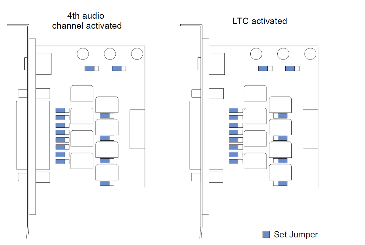
If available, check the jumper settings of the audio panel that should be installed as the audio panel #2. They should be set as the indicated in the left drawing (figure above, 4th audio channel activated). After checking and, if appropriate, adjusting the jumpers of the audio panels to their correct settings you can go on with the next step and install the board into the computer system.
Installation of the Panels
As the third step you have to connect the delivered panels internally to the Atomix LT board and install them in your computer system. For this perform the following: Remove as many slot brackets as you need for the additional panels. Now install the panels: Insert the panels of Atomix LT into the empty slots and fasten each with a screw from the slot brackets. Connect the cables to the appropriate Atomix LT board interfaces as detailed in the following:
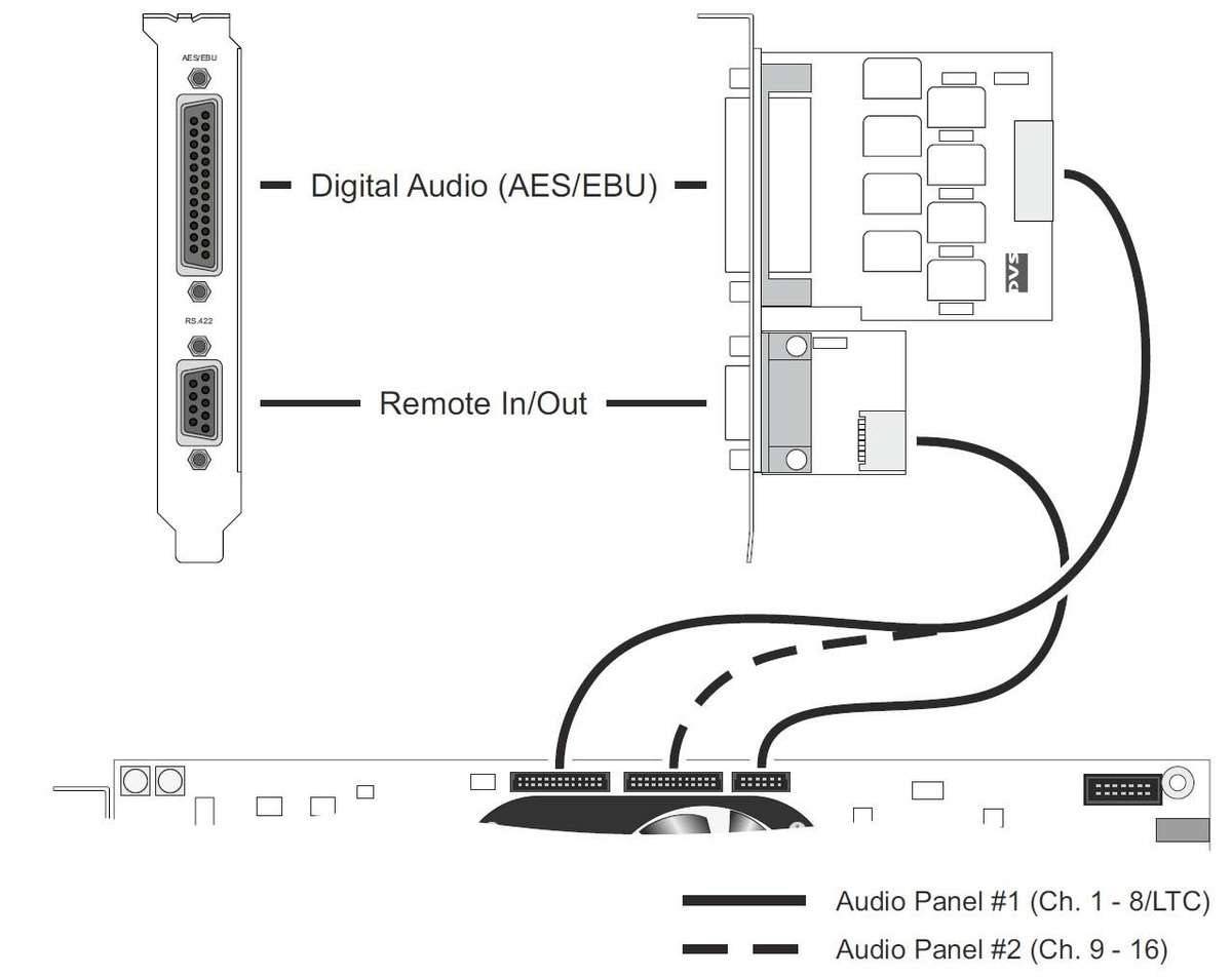
Connecting the Audio and RS-422 Panel
Depending on your setup the audio and RS-422 panel can be installed as the audio panel #1 or 2 (see section “Overview”). The connection is made with a 26- pin flat cable to the Atomix LT board. The remote control connection is made with a 12-pin flat cable. Perform the internal connections as shown in the following figure: Prior to the installation of the panel you have to set/check the jumpers on the printed circuit boards for the appropriate settings (see section “Jumper Settings of the Audio and RS-422 Panel”).(Figure 3.3).
Connecting the Audio Panel(s)
Depending on your setup the audio panel(s) can be installed as audio panel #1 and/or audio panel #2 (see section “Overview”). The connections are made with 26-pin flat cables to the Atomix LT board. To perform the internal connections you can connect the audio panel(s) to the board as shown in the following figure: Prior to the installation of the panels you have to set/check the jumpers on their printed circuit boards for the appropriate settings (see section “Jumper Settings of the Audio Panel(s)”) (Figure 3.4).