MoSys eCrane Setup
MoSys eCrane - Setup and configuration

MoSys eCrane
Setup and configuration
|
DATE |
19/03/2018 |
|
PRINCIPAL AUTHOR |
Jerry Clark |
|
VERSION |
V1.0 |
|
UPDATE |
|
|
MISC |
Docs style applied Dec 2020 |
1.0 Introduction
This document is intended as guide for setting up and operating the MoSys eCrane with tOG VR to produce VR/AR graphics.
The MoSys seCrane is capable of taking jib lengths of between about 1.5m and 3.5m and has been specifically designed for VR use. With careful setup extremely good results can be obtained with tOG VR.
2.0 Setup Check List
Each item in this list is covered in detail in subsequent chapters.
- Connect up the tOG PC to the eCrane and ensure all data is being received correctly
- Take measurements from eCrane and enter into tOG
- Locate eCrane in its operating position and level using foot-screws.
- Carry our the End-Stop and CCD-Centring procedures
- Carry out GAP procedure to establish position and orientation of eCrane relative to known positions.
Special Consideration
Once you have successfully completed step 1. above please pan the camera so that it is directly in-line with the jib and tilt the camera until it is exactly horizontal – you may need to use a spirit level to ensure it is horizontal. Then read and make a note of the Pan and Tilt values as described in the “Check tOG is receiving correct data” step described in Chapter 3.0. If both the pan and tilt values are not VERY close to 0.000 please contact jerry.clark@rtsw.co.uk for further advice.
3.0 Connect tOG PC to eCrane
Connection Diagram
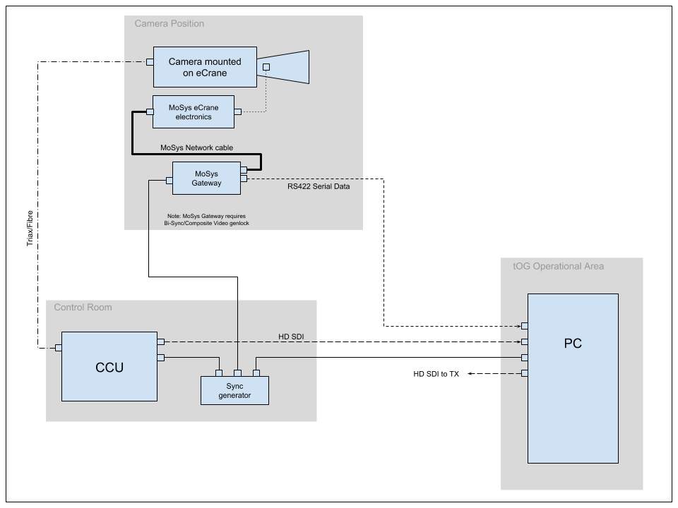
tOG connects to the eCrane via an RS422 serial cable.
RS422 to XLR Cable for Serial Data
To connect the RS422 serial data from the MoSys Gateway into the PC RTSW recommend the use of an XLR tie line.
The data is available on the MoSys Gateway via a female 9-pin d-type connector and a short convertor cable is required to convert this to an XLR connector:
Convertor Cable for MoSys Gateway to XLR
|
Connector |
9-Pin male D-type |
3-Pin female XLR |
|
TXA Pin |
2 |
3 |
|
TXB Pin |
7 |
2 |
|
Earth Pin |
1 |
1 |
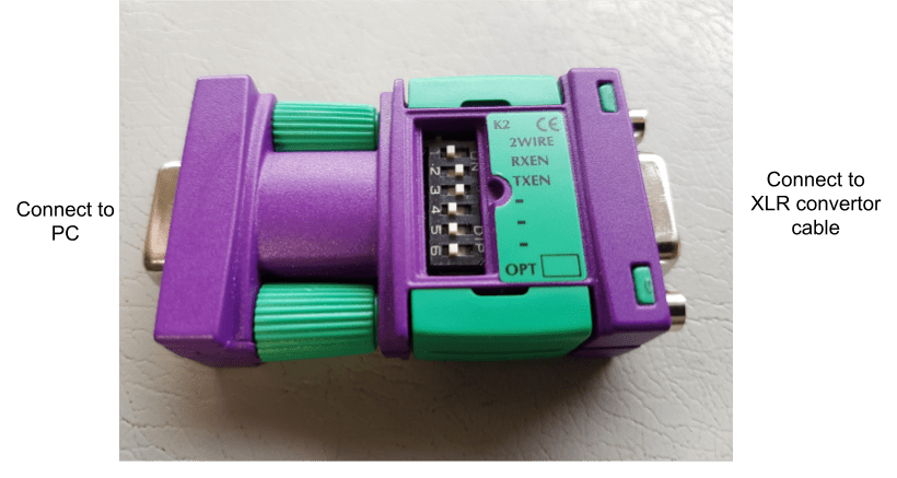
At the PC end the serial port on the PC is an RS232 port so an RS422 to RS232 convertor needs to be used. RTSW recommend the KK Systems K2 device (see below). This convertor has a female 9-pin d-type socket to accept the RS422 data and a convertor cable is required to convert the XLR connector to a male 9-pin d-type connector.
Convertor Cable for XLR to KK Systems K2
|
Connector |
3-Pin male XLR |
9-pin male D-type |
|
TXA Pin |
3 |
2 |
|
TXB Pin |
2 |
7 |
|
Earth Pin |
1 |
1 |
KK Systems K2
Genlock
It is extremely important that the MoSys Gateway is genlock to the same timing as the camera and the tOG PC. Please note the MoSys Gateway requires a Bi-Level (composite video) Black&Burst genlock signal.
Check tOG is receiving correct data
Once all connections have been establish start the tOG software using the Playout interface (a project will need to be loaded).
From the “Setup VR” menu select the correct Tracker Type, Lens File, End Stop file, Serial Port name and Lens Correction file:
Check that the “Date”, “Video” and “Sync” LEDs on the tog interface are all green and then select the”VRData” tog in the “VR Setup” menu.
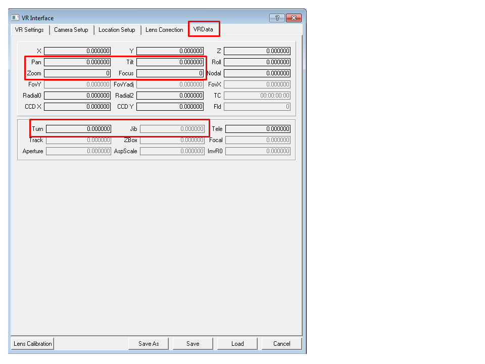
Now move each axis in turn.
- When the camera is panned to the left the “Pan” field should increase (or get less negative)
- When the camera is tilted upwards the “Tilt” field should increase (or get less negative)
- When the camera is zoomed the Zoom field should change
- When the camera is focussed the “Focus” field should change
- When the crane is panned to the left the “Turn” field should increase (or get less negative)
- When the crane is tilted down the “Jib” field should increase (or get less negative)
4.0 Measurements Required from eCrane
Before tOG can be used with the eCrane 5 measurements need to be taken and entered into tOG. These should be measured as accurately as possible – to the closest mm – and entered into tOG in metres. As a reminder 1mm = 0.001m
The schematics below show the measurements that need to be taken.
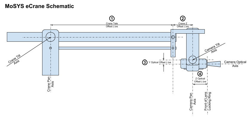
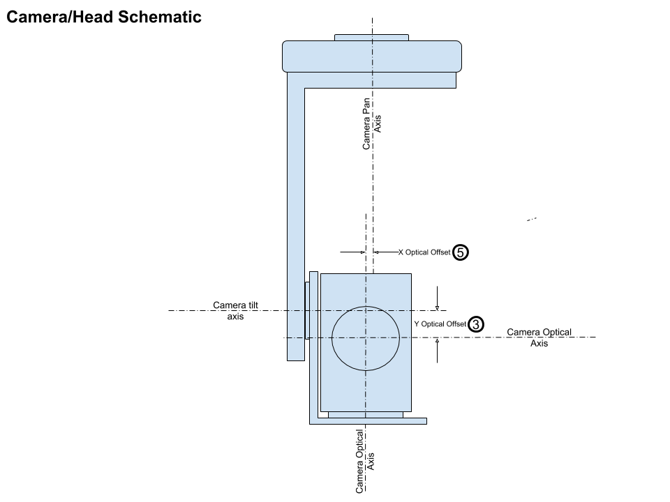
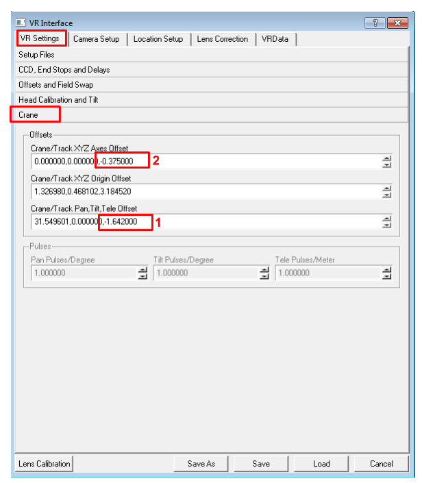
- This is essentially the length of the jib. It could be anything from about 1.5m up to 3.0m. It should always be entered into tOG as a negative number into the “Crane/Track Tele Offset” field (example below shows -1.642m).
- This is the length of the horizontal end of the crane which is normally 375mm for a standard MoSys eCrane. It should always be entered into tOG as a negative number into the “Crane/Track Z Axes Offset” field (example below shows -375mm, -0.375m).
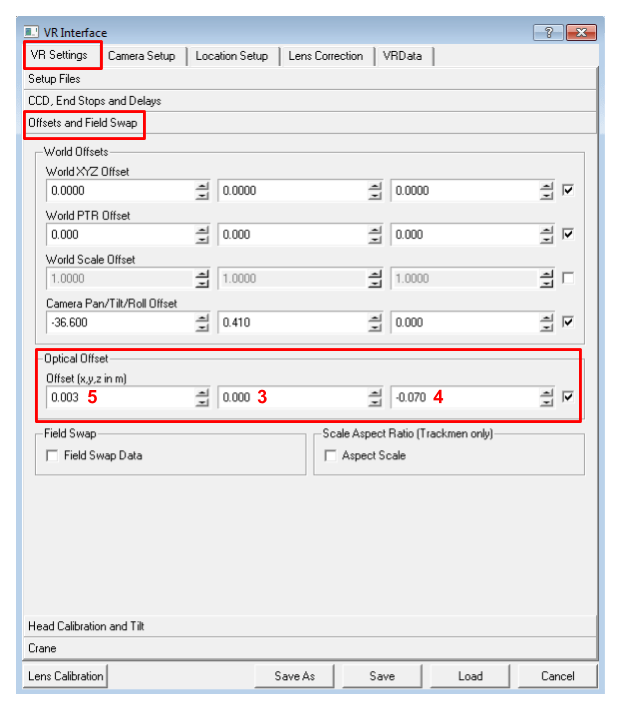
- This is the Y Optical offset and is normally close to zero. If the camera optical axis is above the tilt axis it should be entered as a positive number. If the camera optical axis is below the camera tilt axis it should be entered as a negative number (example below shows 0.000m).
- This is the Z Optical offset and is normally somewhere between 50mm and 150mm. It should be entered as a negative number (example below shows -70mm, -0.070m).
- This is the X Optical Offset and is normally very close to zero. (example below shows 3mm, 0.003m).
When entering these values do not forget to hit <return> after typing the value.
5.0 Positioning and leveling the eCrane
Locate the eCrane base at the position that it is going to be used from and then wind down the 3 foot-screws located on each “arm” of the tripod dolly. Please note that for accurate AR graphics the entire weight must be taken off the wheels and the crane only supported on the foot screws.
Leveling
For good results the foot screws must be adjusted until the crane pan axis is exactly vertical. To enable this there is a high-precision leveling bubble in the “yoke” that forms the crane tilt axis.
The foot screws must be adjusted with the bubble in 2 different places:
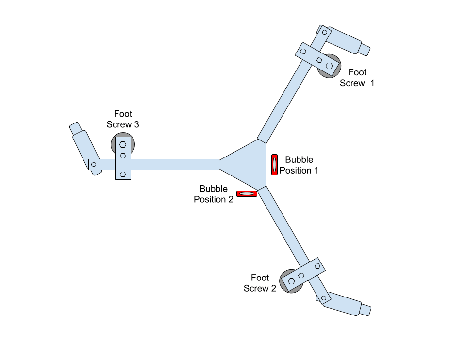
- Pan the crane until the bubble is in Position 1 as shown above. Now adjust Foot Screws 1 & 2 until the bubble shows level.
- Pan the crane until the bubble is in Position 2 and adjust Foot Screw 3 until the bubble shows level.
- Repeat steps 1 and 2 to check crane is level.
6.0 End-Stop Procedure
The End-Stop procedure ensures that tog knows the full extent of the zoom and focus movement of the lens. Incorrect End-Stop settings result in increased drift between virtual and real objects as the lens pans past them.
From the “Setup VR” menu select the “VR Settings” tab and then the “CCD, End Stops and Delays” section.
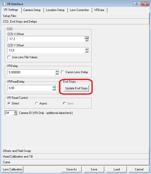
To start the End-Stop procedure click on the button labelled “Update End Stops”. A menu will pop up – please follow the instructions.
For long lenses it is recommended that when moving the zoom from end-to-end its best done at the top speed of movement (the maximum speed of zoom can be set from the lens zoom controller) and the lens is zoomed in and out and least 10 times.
7.0 CCD Centring
In a real camera the centre of zoom is rarely at the centre of frame. Unless the VR camera uses the same centre of zoom as the real camera VR object will appear to drift in relation to real objects as the lens is zoomed. The CCD centring process allows the centre of zoom of the VR camera to be adjusted so that it matches that of the real camera.
To carry out the CCD centring process the camera operator needs to see the tog output – either via the camera return feed or on a separate monitor.
From the “Setup VR” menu select the “VR Settings” tab and then the “CCD, End Stops and Delays” section.
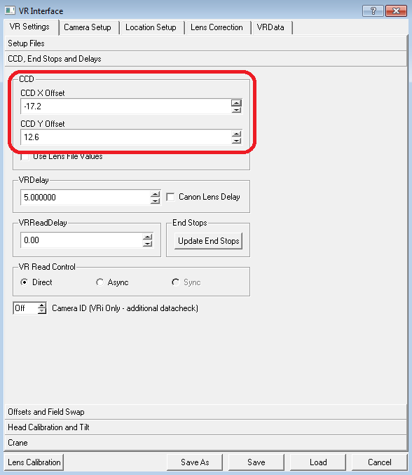
The CCD section has entries for the X Offset and the Y Offset. Clicking on either of these will cause tog to render a cyan crosshair at the current centre of zoom. The camera operator should line this cross up with a well defined corner of a real object with the lens at full zoom. Once the cross-hair has been aligned with a well-defined corner the pan and tilt should be locked off. The lens zoom should now be changed to its “full-wide” position. If the CCD centring is correct the cross-hair should still be aligned with the corner object. If it is not then the tog operator should adjust the CCD offsets in X and Y until the cross-hair is again aligned with the well-defined corner object.
The lens should now be zoomed to full zoom and the position of the cross-hair checked. If it is still lines up with the corner object then the CCD centring is complete. If not then repeat the above procedure. It should only require a single repeat for the cross-hair to remain in the same place as the lens is zoomed in and out. Click on Save to save the new settings.
If either of the values is much greater than about 60 this can indicate a problem with the lens or camera. The lens should be removed from the camera and re-fitted and the CCD centring adjusted again. If either of the offsets is still much greater than 60 then its likely that the lens had been dropped or damaged in some way and this may cause further problems – usually increased drift between real and virtual objects.
8.0 The GAP Procedure
The GAP procedure is how tOG locates the eCrane relative to where the graphics are going to be displayed. Throughout this chapter I will assume the the AR graphics are to appear on a table top and on the floor adjacent to the table.
The GAP procedure requires 6 points that have known X,Y,Z coordinates. Because we are putting graphics on a tabletop it would be sensible to make the 0,0,0 point the centre of the table and base the coordinate system around this.
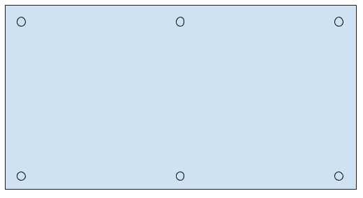
To locate 6 points we could use the 4 corners of the table and mark additional points mid-way along each long edge of the table. For this theoretical example I’m going to assume that the table surface already has 6 “disks” on it that are actually a part of the table surface design.
So the table top looks like this:
Creating a Data File
Using the above example we need to measure the positions of the “disks” and create a data file that can be read into tOG so that tOG knows the points being used.
Suppose the dimensions are as shown below:
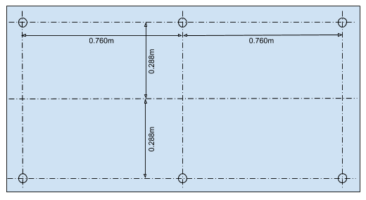
The data file contained 1 “point” per line and has 9 columns of data:
|
Column |
Name |
Description |
X coord |
Y coord |
Z coord |
Pos 1 |
Ref |
Pos 2 |
Pos 3 |
|
Example |
one |
Bottom left |
-0.760 |
0.0 |
0.288 |
1 |
0 |
1 |
0 |
Where:
- Name: the unique name for that point
- Description to describe where it is
- X coord the X coordinate of that point
- Y coord the Y coordinate of that point
- Z coord the Z coordinate of the point
- Pos 1 1=used in GAP position 1, 0 = not used in GAP position 1
- Ref not used but one line MUST have the value 1, all other lines are 0
- Pos 2 1=used in GAP position 2, 0 = not used in GAP position 1
- Pos 3 1=used in GAP position 3, 0 = not used in GAP position 1
And the full table would look like:
|
one |
Top left |
-0.760 |
0.0 |
0.288 |
1 |
0 |
1 |
0 |
|
two |
Top middle |
0.0 |
0.0 |
0.288 |
1 |
1 |
1 |
0 |
|
three |
Top right |
0.760 |
0.0 |
0.288 |
1 |
0 |
1 |
0 |
|
four |
Bottom left |
-0.760 |
0.0 |
-0.288 |
1 |
0 |
1 |
0 |
|
five |
Bottom middle |
0.0 |
0.0 |
-0.288 |
1 |
0 |
1 |
0 |
|
six |
Bottom right |
0.760 |
0.0 |
-0.288 |
1 |
0 |
1 |
0 |
And tog will require a text file that looks like this:
|
“one” |
“Top left” |
-0.760 |
0.0 |
0.288 |
1 |
0 |
1 |
0 |
|
“two” |
“Top middle” |
0.0 |
0.0 |
0.288 |
1 |
1 |
1 |
0 |
|
“three” |
“Top right” |
0.760 |
0.0 |
0.288 |
1 |
0 |
1 |
0 |
|
“four” |
“Bottom left” |
-0.760 |
0.0 |
-0.288 |
1 |
0 |
1 |
0 |
|
“five” |
“Bottom middle” |
0.0 |
0.0 |
-0.288 |
1 |
0 |
1 |
0 |
|
“six” |
“Bottom right” |
0.760 |
0.0 |
-0.288 |
1 |
0 |
1 |
0 |
Note: That all the text items need to be enclosed in double quotes (“).
For this example let assume we create a text file called “Table.txt” and it has the above lines in it.
Two Point GAP
The GAP procedure is done with the eCrane on two positions – ideally the eCrane jib is panned by 90 degrees clockwise between the 2 positions but as long as its panned clockwise any angle between about 60 degrees and 120 degrees is acceptable.
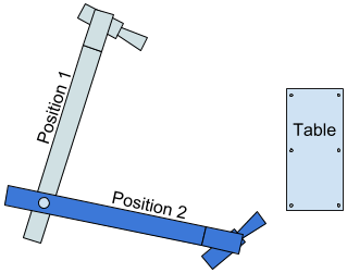
At each position the jib must be precisely leveled using an adjustable stand. A heavy weight should be placed on the jib above the stand and there is a high-precision leveling bubble on the top surface of the jib.
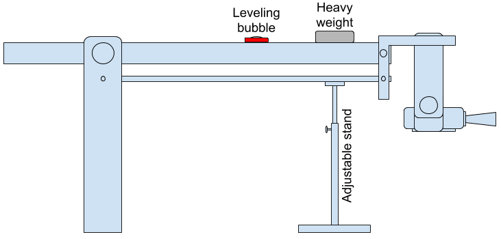
At each position the stand should be adjusted until the bubble is showing exactly level.
Procedure Steps
- Ensure all data is being received correctly as in Chapter 3.0
- Create the file “Table.txt” containing the coordinates of the markers on the table top as described above.
- Enter the measured values from Chapter 4.0
- Position the eCrane, wind down the foot screws and go through the leveling procedure as in Chapter 5.0
- Carry out the End-Stop and CCD Centring procedures described in Chapters 6.0 & 7.0
- Pan the jib to Position 1 and level the jib as described above.
- In tog click open the “VR” menu and select the “Camera Setup” tab. See below:
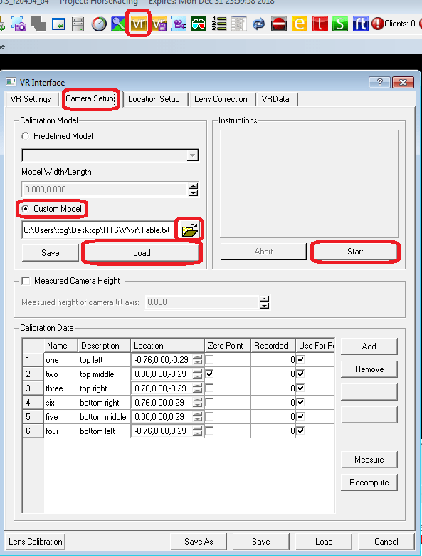
- Tick “Custom Model”, browse for and select the “Table.txt” file and click on “Load” and then click on “Start”.
- There will now be a series of instructions and pop-ups. Please read and follow them precisely. Be VERY careful not to move the jib – just the camera.
- After pointing the camera at the 6 points and on the table and accepting the calculated camera coordinates you will be prompted to move the jib to position 2 – again just follow the instructions.
- After pointing the camera at the 6 points on the table from Position 2 tog will calculate the crane parameters and ask if you want save them.
- Remove the weight from the jib and test some VR graphics to make sure they stay still when you move the crane/camera
