TacticPro-7.0

Reference Manual
| About | Description |
| Revision | 7.0 |
| History | v1.1 |
| Authors | RTSW Support |

Tactic Pro is an interactive application that allows you to place specifically designed graphics into recorded video. It has various configurations and modes of operation that meet the demands of sports analysts worldwide.
Tactic Pro may be used by presenters live on air to enhance discussions and analysis of sporting moments.
Tactic Pro can work with either internal, file based clips or via external baseband SDI video coming from either live sources or from VTR devices using a number of industry standard protocols. Video control is provided via an intuitive VTR control panel on screen.
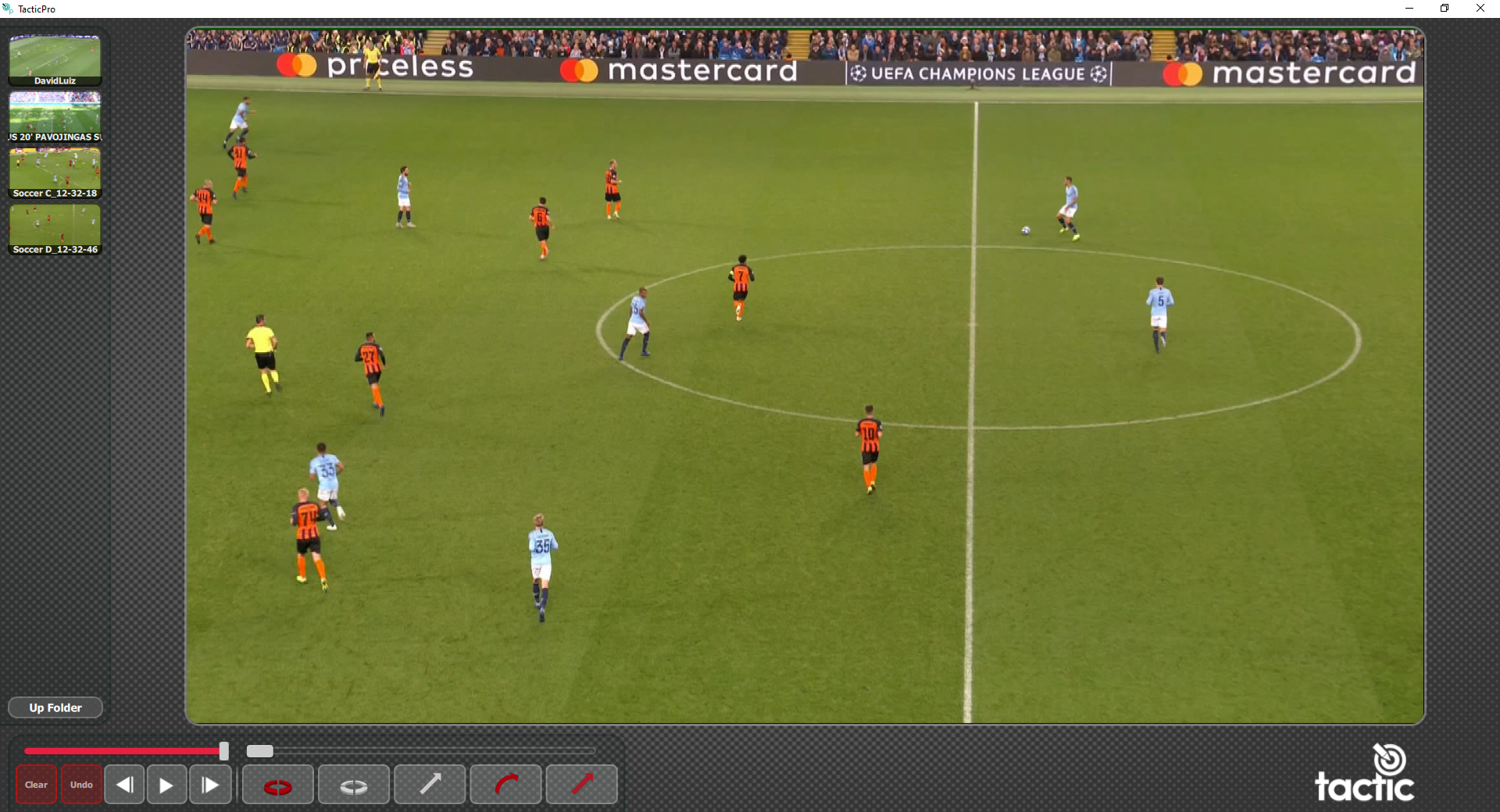
Tactic Pro operates in 3 distinct camera modes. The camera mode dictates how the graphics drawn will appear in relation to the real broadcast camera used to film the footage. These modes are:
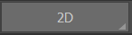
- 2D Camera – This is the simplest of all the modes and the graphics appear flat to the screen.
- 3D Camera – This uses a perspective camera. Graphics will appear on the playing surface and may be keyed between players and grass. You can select from a list of preset camera positions or create your own. These may be used on a freeze or Key Framed to follow the movement of play.
- 3D Image Tracked – In true 3D mode Tactic Pro supports feature based tracking. This allows graphics to be ‘tied-to-pitch’ – even when the camera view moves.
All modes are available instantly.
As well as supplying a set of predefined graphics you can also build your own by combining any of these predefined graphics. These will automatically appear on the user interface.
Keyboard shortcuts are available for many frequently used functions. See Appendix B for further details.
Video Tutorials
Video tutorials are available to assist with installation and using Tactic Pro SP.
https://vimeo.com/showcase/6251661
Installation
General Guidelines
Please observe these guidelines. Observation of these simple guidelines will avoid many typical installation problems.
- The user account name MUST have Administrator rights
- The user account name MUST NOT contain spaces or any non-English characters
- The software can only be used on the PC on which it is installed (no network / fileserver)
- The recommended screen resolution is 1920 x 1080
(1366 x 768 minimum, 3840 x 2160 maximum)
Supported Hardware
Check our website for the latest supported hardware configurations.
See Tactic Hardware Specs.
Tactic is made for broadcast use on Windows 10 and 11×64 platforms.
Nvidia Graphics Card and Drivers
If not already installed with the operating system, these may be obtained from the nVidia website www.nvidia.com and are specific to the hardware installed in your PC.
AJA Video Card and Drivers
To send and receive video an AJA video card is required.
Always use the AJA driver version that is available with the installed version of Tactic Pro.
If you are re-installing or updating then refer to the uninstall section below before attempting a reinstall/update.
Locate the appropriate driver from the RTSoftware web site or FTP site.
You will need an authorised login to access this site. If you do not have one then please contact support@rtsw.co.uk.
DO NOT INSTALL AN AJA DRIVER FROM THE AJA WEB SITE UNLESS EXPLICITLY DIRECTED TO BY RTSoftware
RT Software Security
Tactic Pro is Licensed using one of the following methods.
1 – Software License (SL)
A software License key installed on the PC.
A Trial License is available upon request from RT Software https://www.rtsw.co.uk/
To obtain a software License, contact sales@rtsw.co.uk
2 – USB Security Key – Hardware License (HL)
The USB Security key (dongle) must be inserted in a USB port of the PC at all times.
To obtain a USB Security key (dongle), contact sales@rtsw.co.uk
NOTE: See the relevant sections in the Appendix to request / install / update or transfer the License.
Download the Installers
Tactic Pro is available to download from our website: https://rtsw.co.uk/software-downloads/#tab-2
Please contact support@rtsw.co.uk if you have any questions.
The Tactic Pro installer has the following file name: tacticpro-7.0.0_rxxxxx-windows-installer.zip
Installation
Once you have downloaded the necessary installer you are ready to proceed.
tacticpro-7.0.0_rxxxxx-windows-installer.zip
Unzip the file and run the installer, accept all defaults and conditions and click

as required.
Reboot your PC
Users Desktop
The installation process will have created an RTSW folder on the users desktop. See Appendix E for moving the RTSW folder.

NOTE: Do NOT delete this folder.
This RTSW folder will contain the Tactic Pro project folder etc..
The installation process will have created a Tactic Pro shortcut on the user’s desktop.
e.g.
Uninstall
To uninstall Tactic Pro run the uninstaller in the RTSW folder.
or
Use the system “Settings” tools, “Control Panel” or “File Explorer”.
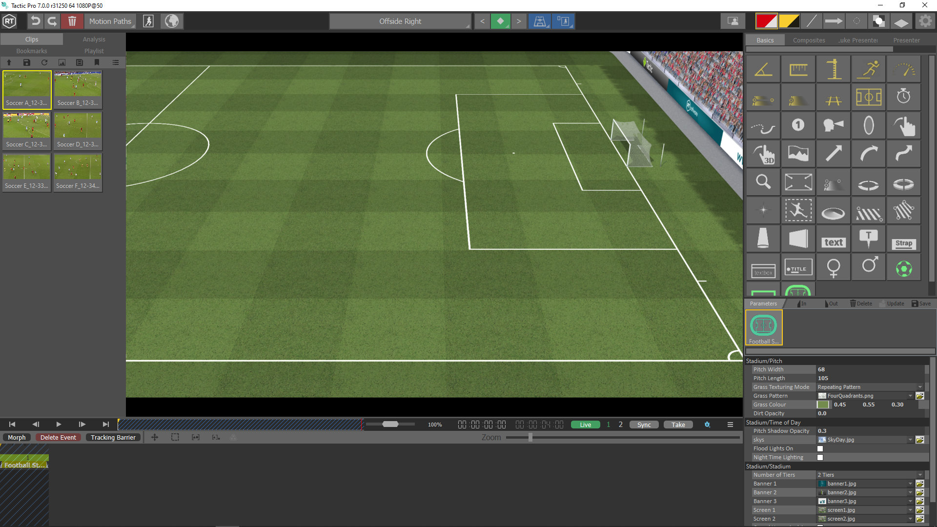
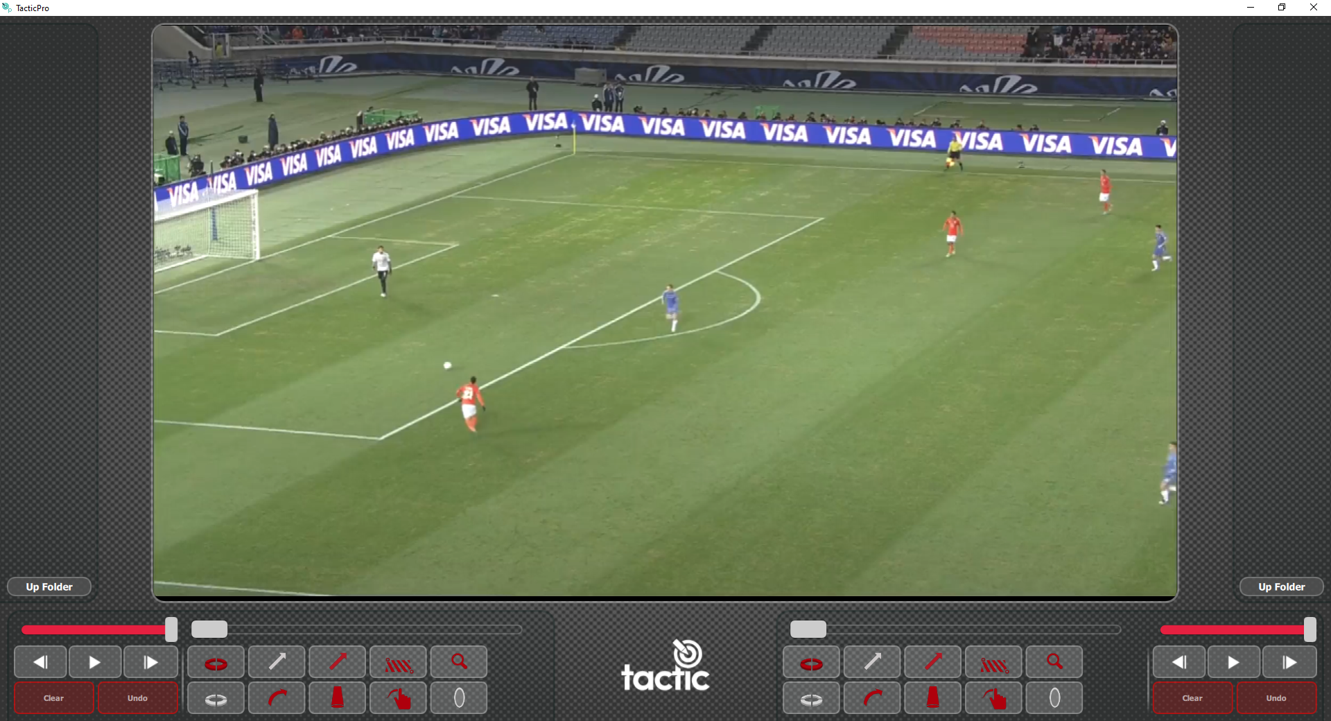
Interface Overview

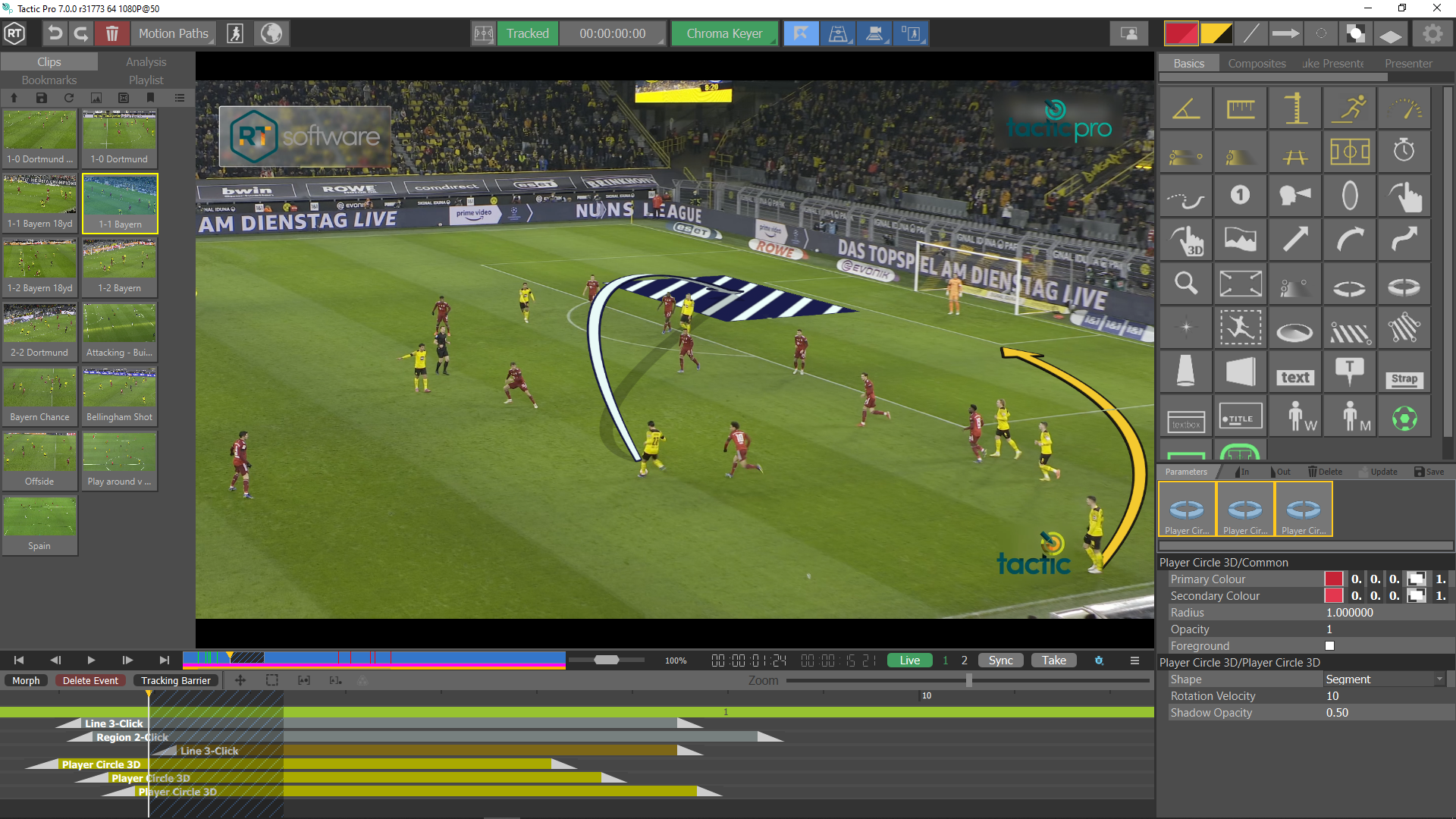


- Toolbar
- Undo/Redo
- Clear
- Motion Paths
- Grid
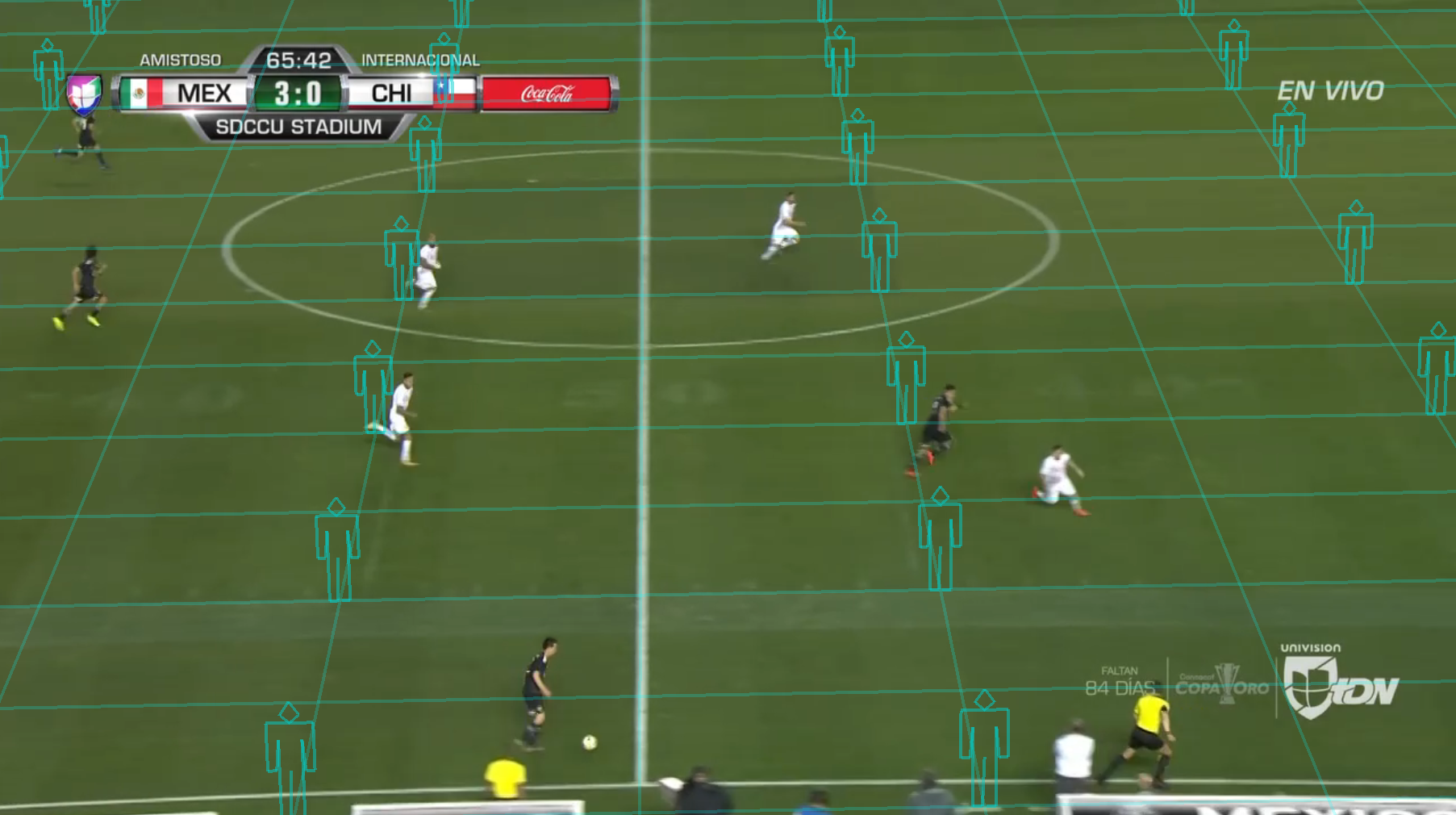
- Traced/Untracked Graphics
- Cameras
- Keyer
- Set Auto Chroma keyer
- Auto Pitch Calibration
- Auto Track
- Player Detect
- Preferences
- Video
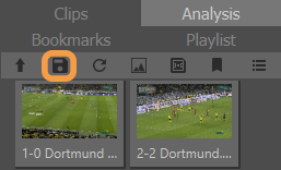
- Clip Browser
- Clips
- Analysis
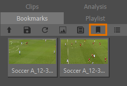
- Bookmarks
- Playlist
- VT bar
- Play/Pause/Rewind/etc
- Seek bar
- Timeline
- VT Context Menu
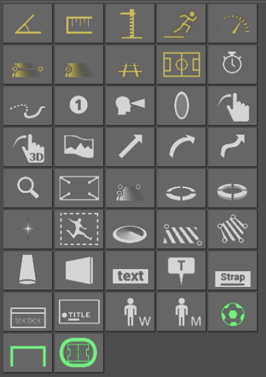
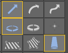
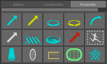
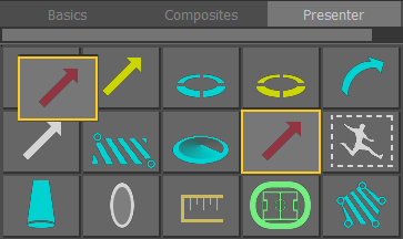
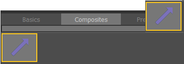
- Graphics
- Basic Graphics
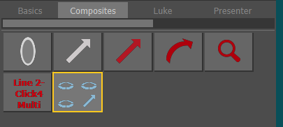
- Composite Graphics
- Presenter
- Text
- Parameters
- Appearance/Style
Basic Configuration
Select Sports Package
Tactic Pro includes multiple predefined Sports Packages.
A Sports Package contains a project with sports specific graphics. On startup, if more than one Sports Package is installed, you will see a dialog asking you to select the Sport that you wish to analyse.
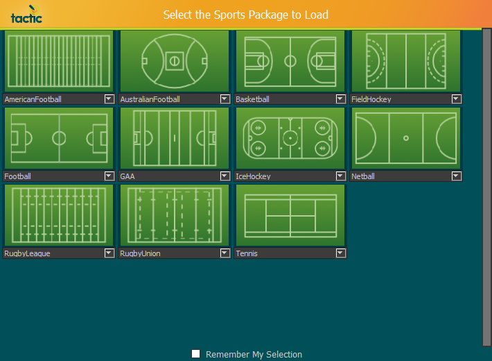
If you always use the same sport, select Remember My Selection.
Select the Pitch representing the required Sport.
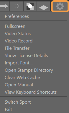
The selected sport can be changed by clicking on the cog icon (top right) in Tactic and selecting “Switch Sport”.
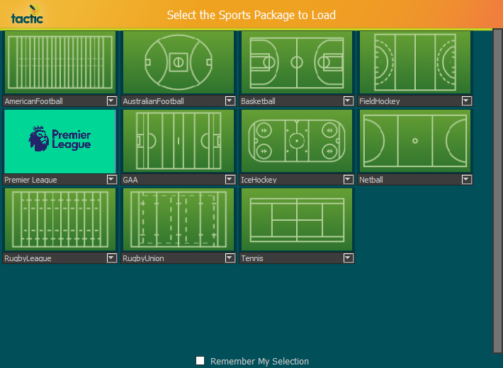
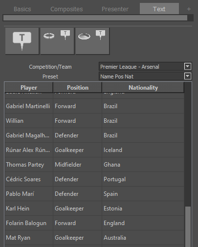
Select League Package
- League packages allow a set of custom defaults dedicated to a particular “League” of the sport of your choice.
- League packages are scanned from the users RTSW folder rather than installed – this means they can be downloaded from the web and created without requiring a new release. (the example below shows the “Premier League” package in the drop- down selection menu), the package was added to: C:Users<Your Username>DesktopRTSWTacticPro
- League packages can consist of all of the default data that exists in a Sports package:
- Composite styles
- Presenter Page layout
- Default palette with suitable colour combinations.
- Custom Camera list.
- Text files for the new text entry tool.
- A customised icon that appears on the package selector page to identify this league
- Custom badges based on the league
Creating a League Package
Creating a Package or Template
There are two types of files needed for the league graphic interface to automatically populate a graphic. The ‘package file’ provides the data which is used to populate the graphic, such as the names and positions of the players on a team. The ‘template file’ is used to arrange the raw data into the desired format. Templates use the column names found in packages to know what data to use.
These files are easily generated by entering the data into a spreadsheet and downloading it as a comma separated value file (CSV). The files can then be put into the correct place in the RTSW folder and Tactic will automatically pick them up.
Spreadsheet Instructions
In package spreadsheets the first row of each column should contain a suitable name for the data that is found in that column. The rest of the rows will contain the data. The name of the sheet should be the name of the package as the downloaded csv file will automatically have the sheet’s name.
Template sheets have only two columns. The first column contains the global parameter name that the arranged data will be applied to. The second column contains the pattern to apply to data. This pattern can contain plain text as well as the column names from package files. When referring to a package column name the name must be wrapped in ${name}. Eg, ${player_name} or ${position}.
When a spreadsheet has been filled in you can download it by going to ‘File > Download > Comma-separated values (.csv current sheet). This will download a .csv file with the same name as that sheet tab. Each sheet must be downloaded individually.
RTSW Folder
Each league you load will have its own folder in the main folder for the version of tactic you are using. eg ‘rtsw/tacticpro/premier league’. This league folder will contain a folder called ‘text’. Package files should be placed here. Each graphic you wish to use a package with should have a folder in ‘text’ with the name of that graphic. Template files go into the folders of compatible graphics.
Package Example:
rtsw/tacticpro/premier league/text/Everton.csv
Template Example:
rtsw/tacticpro/premier league/text/advanced text/name and number.csv
The Default RTSW Folder location is on the Windows Desktop, see Appendix E on how to move the RTSW to a different directory if required.
League Graphic Interface
In Tactic Pro you will find a style page called ‘Text’. This page contains the league graphic interface. The top section shows the styles which have been found in the loaded projects and have an associated folder in the ‘text’ folder. The package combo box shows the packages which have been found. The template combo box shows the templates which are available for use with the current package. If a template contains ${} variables which aren’t found in the current package the template will be unavailable for use with that package. The table area shows the package data arranged according to the template.
Selecting a different style from the top section options will reload the packages. Selecting a package will reload templates.
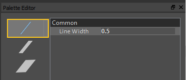
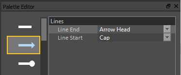
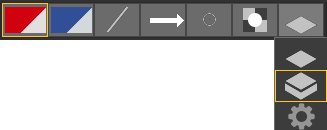
Editing a Palette in Tactic Pro
Palettes can be edited inside of Tactic. Clicking and holding on a palette icon will open the full palette menu. The cog icon at the bottom will open the palette editor interface. This interface shows a list of all palettes down the left side. Clicking an icon will populate the top text field with the palette’s name and display the parameters that the palette sets. Changes made here are automatically saved. See “Colours” for more information.
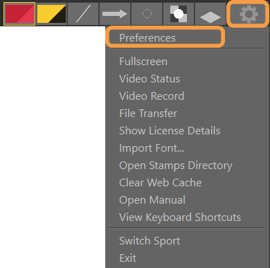
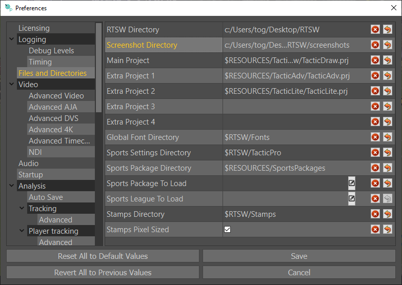
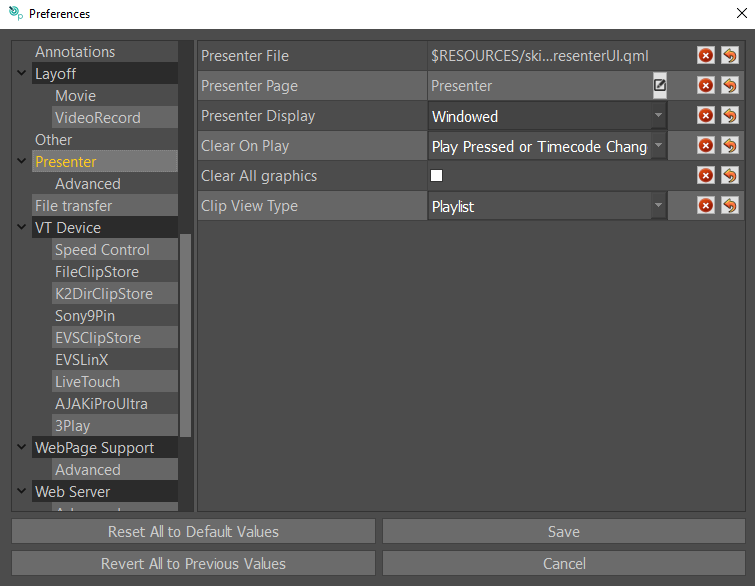
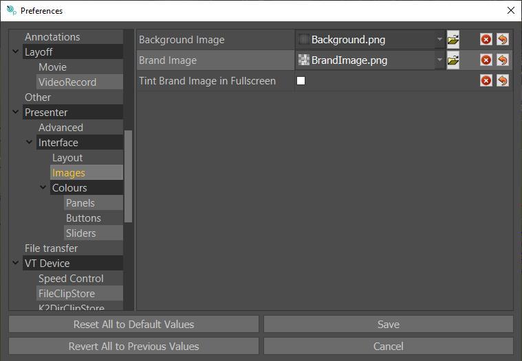
Preferences
Select the “gear” icon in the top right corner and select “Preferences” …
For details of all application Preferences see Appendix A in this document.
User Data
All user data and application Preferences are stored in a single folder on the users desktop.
Each sport/League Package has its own subfolder. This includes Analysis, Composite Styles, Cameras and palettes.
This ensures that each sport can be configured independently, and any sport specific analysis tools are separated.
e.g. DesktopRTSWTacticPro
Within each sport/League Package folder are preferences for that sport
Initialisation File
Your settings can be reset to default by renaming this file, you can rename it back to the original name to restore it.
C:UsersYourUserNameAppDataRoamingRTSoftwaretacticpro.ini
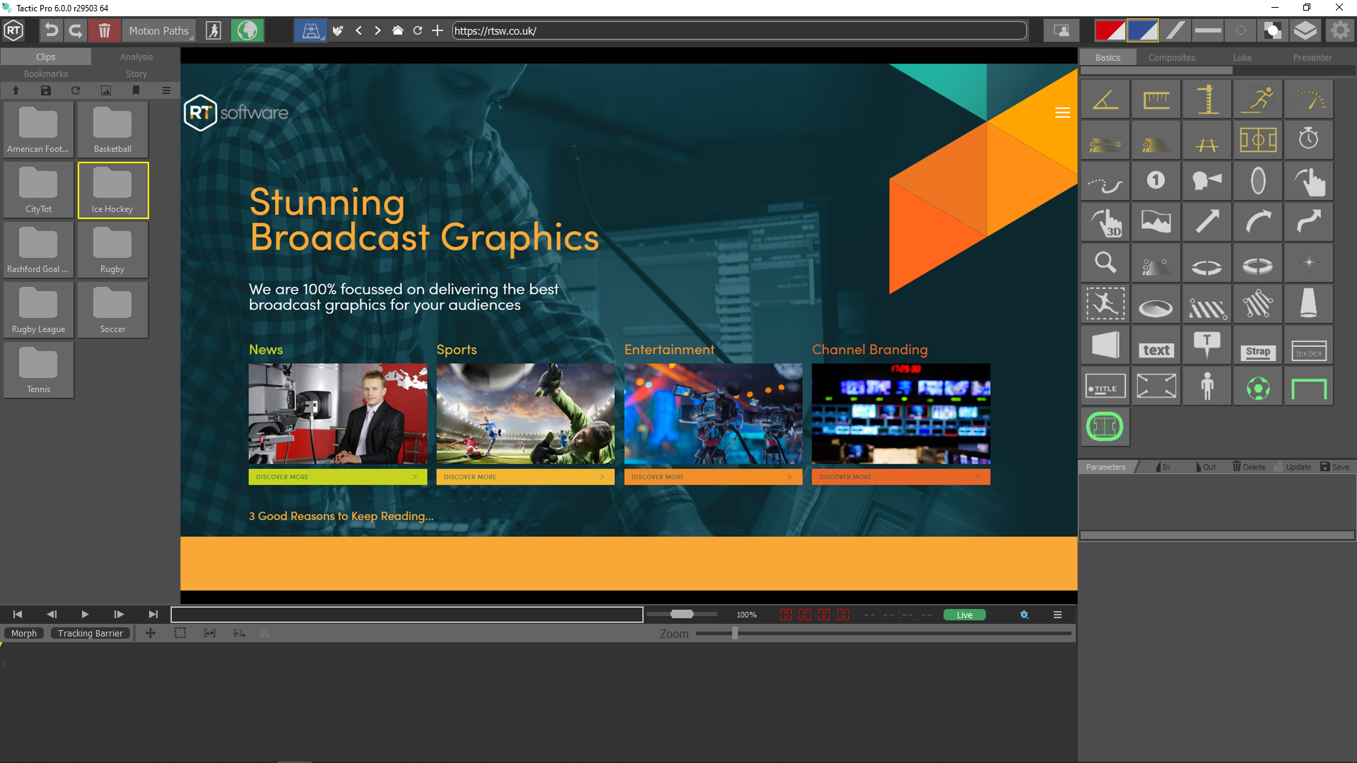
Clip Browser
Thumbnails of all stored video clips in the folder specified in Set FileClipStore options.
e.g. DesktopRTSWclips
Select Refresh Clips to update the display
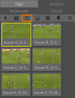
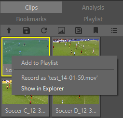
A Right Click on any clip will offer you the “Show in Explorer” option. Selecting this will open a windows explorer window showing the location of the clip.
A left click on any clip will open the clip in Tactic’s video window.
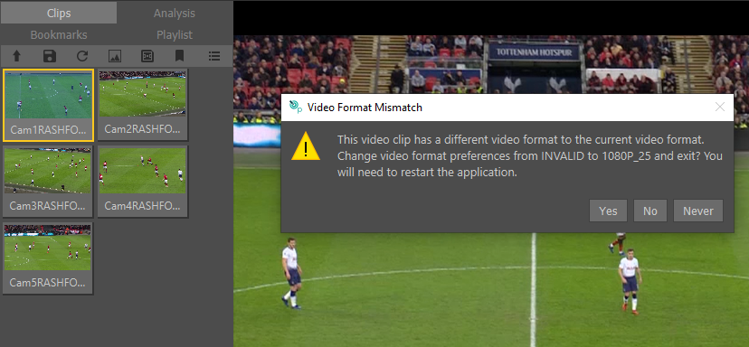
If the selected clip is in a different format to Tactic’s current video format which is displayed in the title bar (also see “Video” in Appendix). the video format mismatch warning message will appear.
Clicking “Yes” will automatically change the Tactic video format to match the selected clip and close Tactic. A restart of Tactic is then required.
Clicking “No” will close the message and load the clip even though it is in the wrong format, you may see that the clip does not play real time speed if the frame rate of the clip does not match the current setting.
Clicking “Never” will close the message and load the clip and the message will no longer be displayed in subsequent mismatches until it is turned on again in preferences. See Advanced Video on how to turn this back on.
If an analysis has been created and not saved, you will see the following message when loading a new clip.
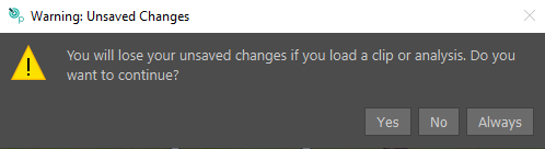
This will give you the option to save the analysis (“Yes”), not save it (“No”) or turn off this message (“Always”). The warning message can be turned on again in preferences, see: “Analysis” in the appendix.
Change Views
You can change between an icon and list views by clicking on:

Icons View
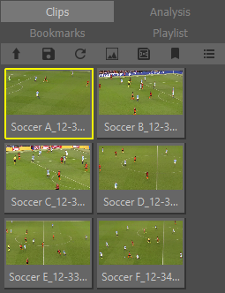
List View
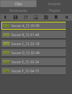
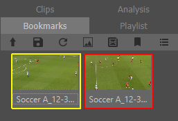
This applies to clips, analysis, bookmarks, and playlists.
VT Controls
The VT Controls are used to Play/Advance/Rewind the video clip.
Rewind to beginning, Step back one frame, Play, Step forward one frame, Fast Forward to end.

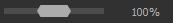
Seek Bar. Drag the vertical line to the desired clip position (Timecode).

Jog video clip backwards or forwards.
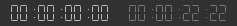
The Timecode for the current video clip position and total duration of clip.
Jump to Timecode
Clicking on the timecode will open the “”Jump To Timecode” menu:
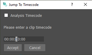
You can enter a timecode using the numeric keys, or by scrolling with the mouse wheel. Pressing accept will move to the specified timecode of the clip, or if “Analysis Timecode” is selected, to the timecode of the analysis file.
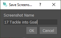
Save Screenshot
This tool allows you to take a screenshot of the current frame including any added graphics. You can name the file in the window prompt that appears when you click on the button
The default screenshot folder can be set in the Preferences menu under Files and Directories in the “Screenshot Directory” option.
Create and analysis without a clip
This function is useful if you wish to create an analysis entirely in the virtual stadium
Click on the ““Create an analysis with no clip (black background) and a stadium graphic button” below.
A pause will be created in the timeline (to the default duration) and the stadium graphic will be added automatically throughout the duration of the pause. The video window will show the virtual stadium view with the most recently used camera.
You are now ready to start adding graphics to the virtual stadium. See the “Virtual Stadium” section.
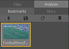
Bookmarks
Use the VT Controls to Play/Advance/Rewind the video clip and create a Bookmark at any point in the video clip that may be useful for future analysis.
Add Bookmark
Add a Bookmark at any position (timecode) within the current loaded clip.
Load Bookmark
Choose and select a Bookmark to analyse from the Clip Browser.
Delete Bookmark
Select the Bookmark, press the “Right Mouse Button” then Delete
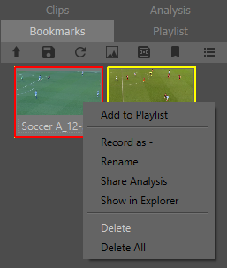
“Add to Playlist ” will add the bookmark to the playlist, see Playlists.
“Record as” will record the bookmark in the same way as is done with an analysis, See Record Analyses with right click.
“Rename” will rename the bookmark.
“Share Analysis” allows the bookmark to be copied to another system as an analysis. See Share Analysis.
“Show in Explorer” will open an explorer window showing the location of the bookmark.
Stamps
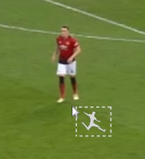
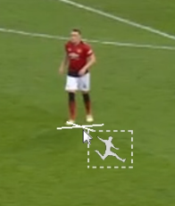
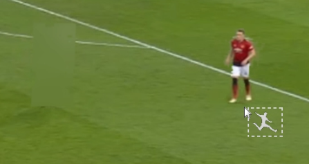
Stamps provide an easy approach to inserting image graphics onto the scene.
Search for the images on your systems file manager and select images
Drag onto the tool box in Tactic

Custom styles are created and stored in the current active tool page or the Composites page if the Basics page was previously active
Web Browser
Select the “Web” Button at the top of the page.

Enter a URL in the URL bar and press Enter to load the web page. Local directories can be used here too to show local images and PDFs.
Graphics can be placed on top of the web page.


To revert to clips, select any clip from the clip library on the left hand side.
URL Bar
The URL bar has tool buttons to help navigate through the web browser.
From left to right:
- Open file
- Open a file to load into the web browser
- Back
- Navigate to previous page
- Forward
- Navigate to next page
- Home
- Navigate to the home page set in preferences under ‘WebPage Support’
- Refresh
- Reload the current web page
- Bookmark Page
- Create a web bookmark (see Web Bookmarks)
Interactivity
Toggle Web mode with the Web button in the toolbar.
With Web mode active, mouse and keyboard inputs will be passed to the web page.
While Web mode is active, placed graphics will not be interactive without deactivating web mode.
Clicking a graphic tool will automatically deactivate web mode.
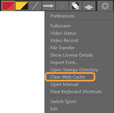
Cache
Web cache is stored while web pages are in use.
Clear web cache by selecting ‘Clear Web Cache’ in the cog menu.
Web Bookmarks
Bookmark a web page with the bookmark button in the toolbar.
Navigate to the web bookmark by selecting the bookmark in the bookmarks page.
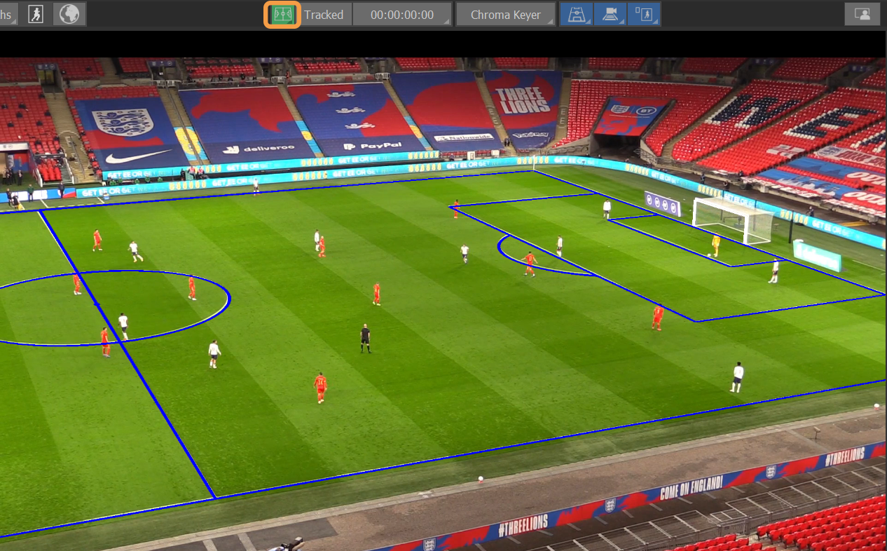
Cameras
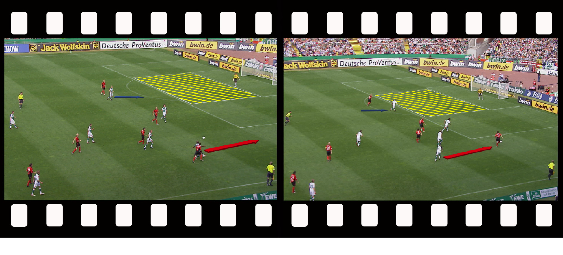
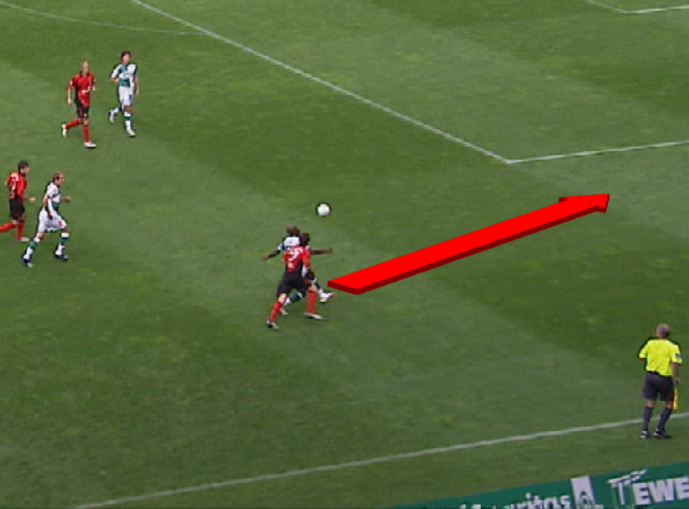
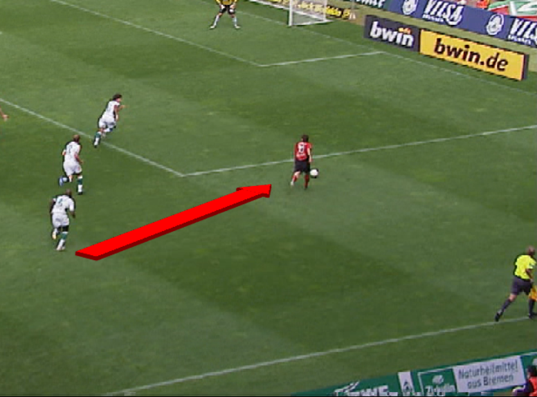
Tactic Pro operates in 3 distinct camera modes. The camera mode dictates how the graphics drawn will appear in relation to the real camera used to film the footage. These modes are:
- 2D Camera – This is the simplest of all the modes and the graphics appear flat to the screen.
- 3D Camera – This uses a perspective camera. Graphics will appear on the playing surface and may be keyed between players and grass. You can select from a list of pre-set camera positions or create your own. These may be used on a “freeze frame” or using the “Motion Path” feature to follow the movement of play.
- 3D Image Tracked – In true 3D mode Tactic Pro supports feature based tracking. This allows graphics to be ‘tied-to-pitch’ – even when the camera view moves.
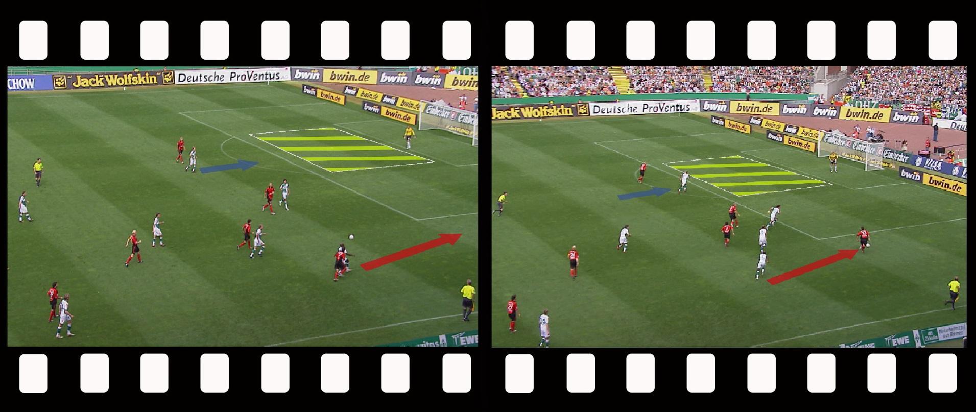
All camera modes are available instantly.
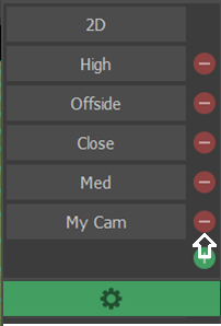
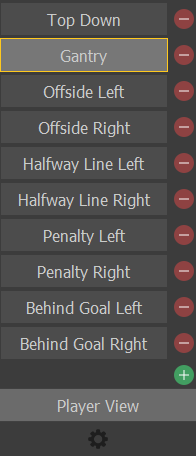
Select Camera
The currently active Camera is displayed on the Toolbar.
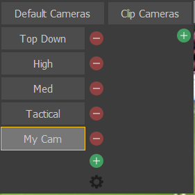
Select and hold the “My Cam” button to display a list of Cameras.

Select the required Camera from the list.
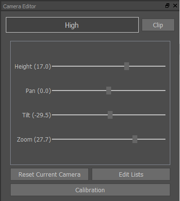
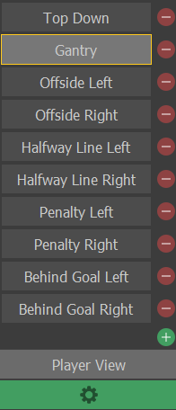
Edit Camera
Select and hold the active Camera to display a list of Cameras.
Select the “gear” icon at the bottom of the list.
A “Render Grid” is overlaid on the video clip.
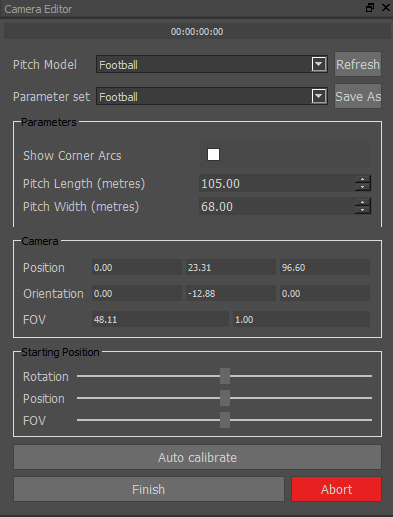
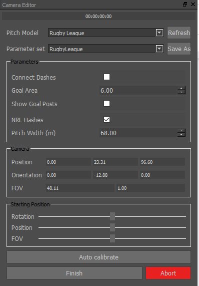
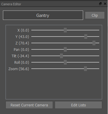
The Camera Editor dialog is displayed.
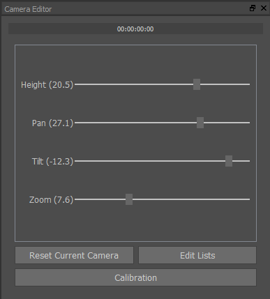
Adjust the grid using the slider bars (or place the cursor over the required slider bar and use the “Mouse Wheel”) so that the view and scale closely align with the video clip.
The perspective of analysis graphics will now scale correctly.
Rename the Camera if required
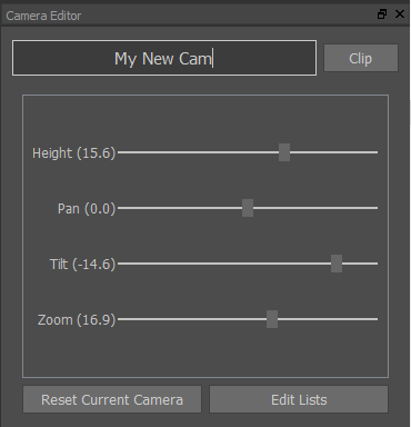
Clip Create a new camera named as the current timecode
Reset Current Camera Reset to the installation defaults
Edit Lists Select and Edit specific camera from the Camera List
NB: If you are working on a sport with a line based pitch, you may be able to use lines to calibrate your camera to match your source camera. See page 103 for details.
Add Camera
Add a new camera using the + symbol
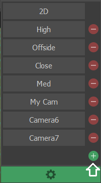
Delete Camera
Delete unwanted camera using the – symbol
Grid
Toggle the Grid display on/off

Keying
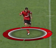
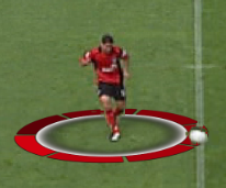
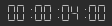
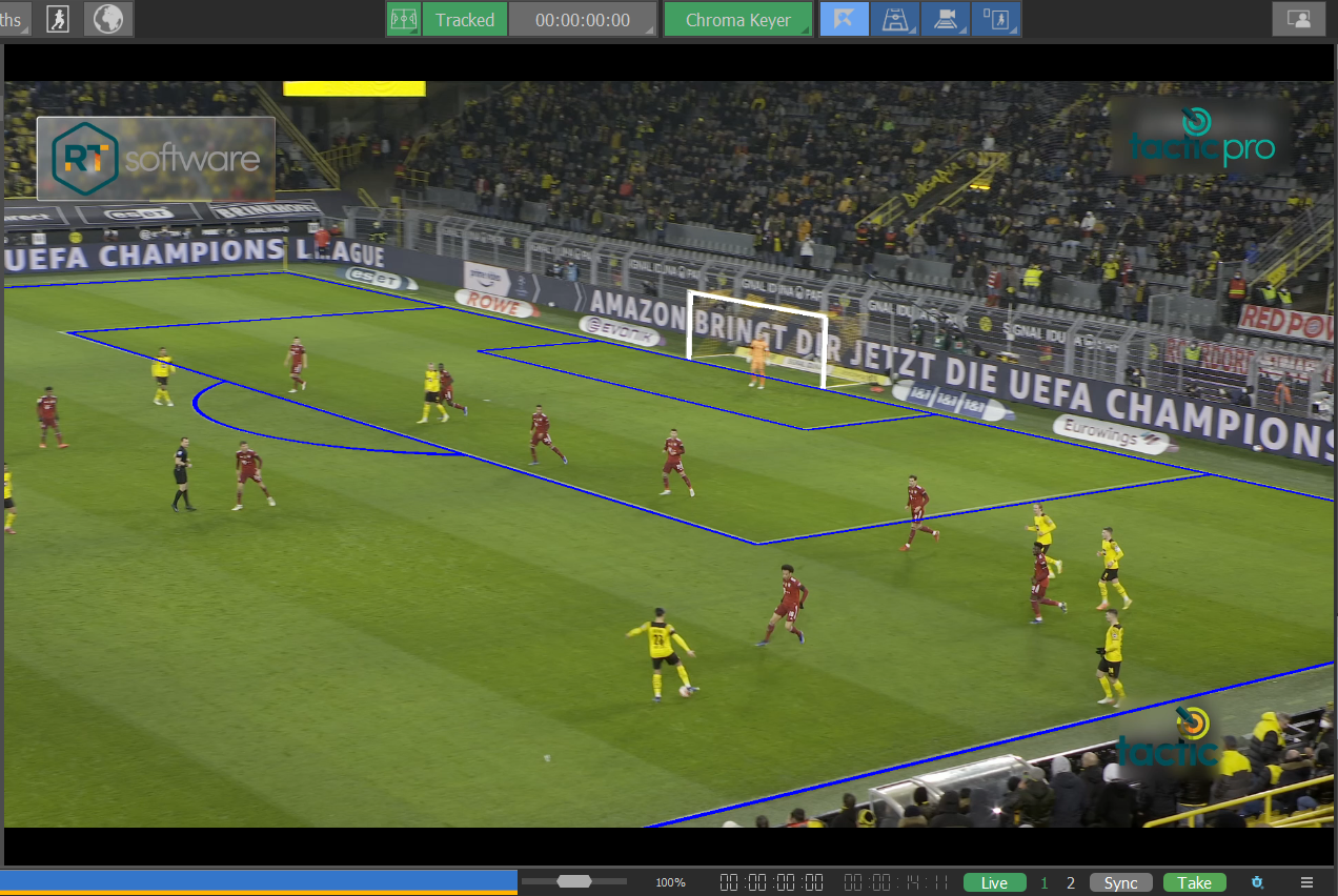
Without a Keyer, graphics appear on top of the players.
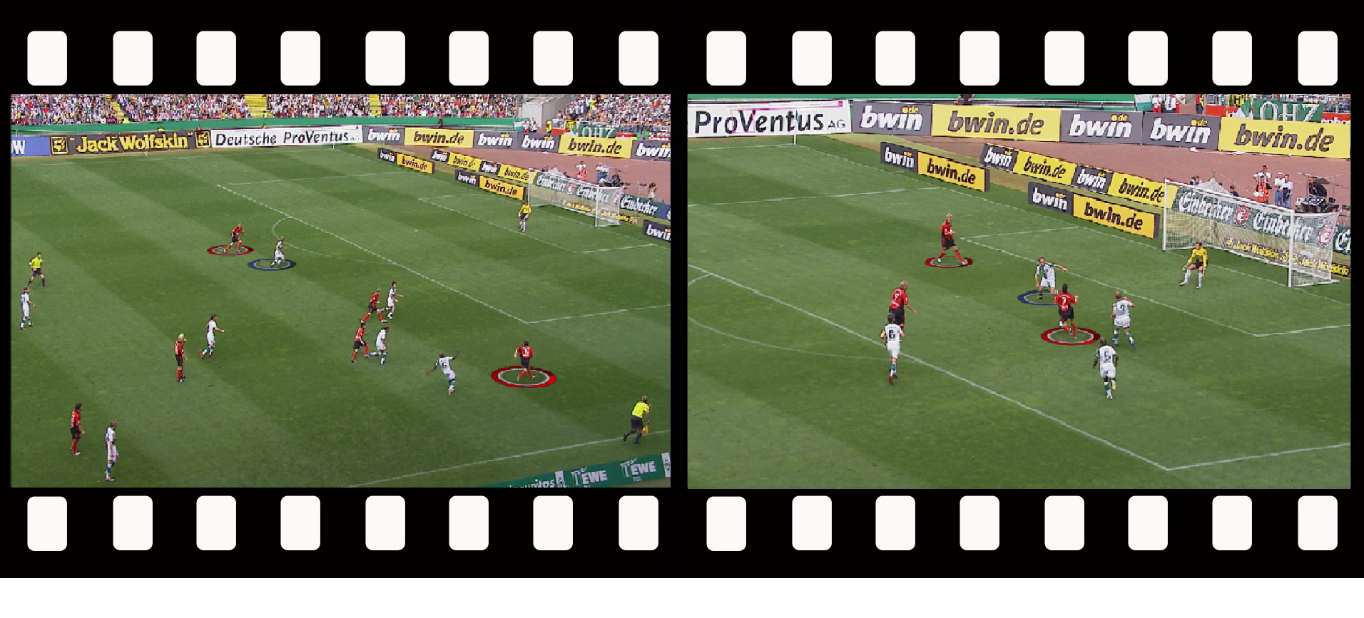
Using a correctly defined Keyer, the players appear in front of the graphics. The graphics now appear to be painted on the pitch surface.
Without Keying With Keying
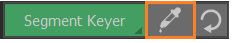
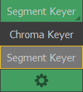
Select Keyer
Select the required Keyer from the list.
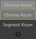
Enable Chroma Keyer
Once Keying is enabled the icon turns green and the Auto Key button is displayed.

Press Auto Key to optimise the settings automatically. The auto key button turns a lighter colour blue when it has been set.
Edit Chroma Keyer
Select and hold the active Keyer to display a list of Keyers.
Select the “gear” icon at the bottom of the list.
The Keyer Editor dialog is displayed.
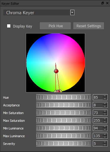
Display Key A Black & White image of the current settings overlayed on the video clip
Pick Hue Manually select the background colour.
Reset Settings Reset to the installation defaults
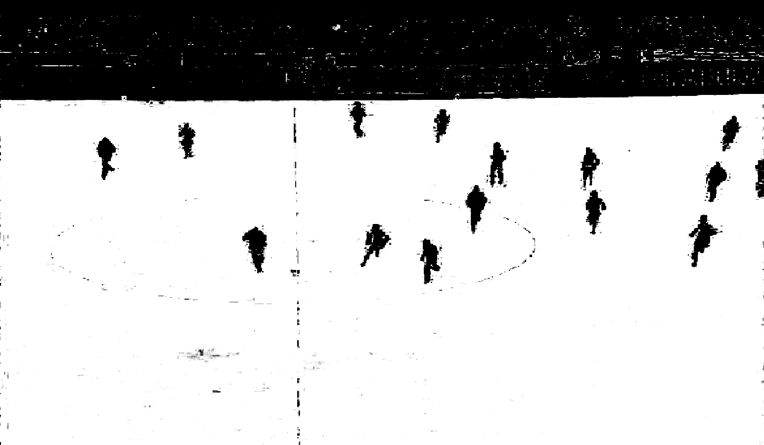
View and adjust the Keyer so that the graphics will only be drawn on the white area and appear behind objects that are black.
Enable Segment Keyer
Once Keying is enabled the icon turns green and the Begin Pick and Reset buttons are displayed.
Press Begin Pick and select the background colour..
Hold the Left Mouse button down and drag the cursor across the video to select the Keyed area.
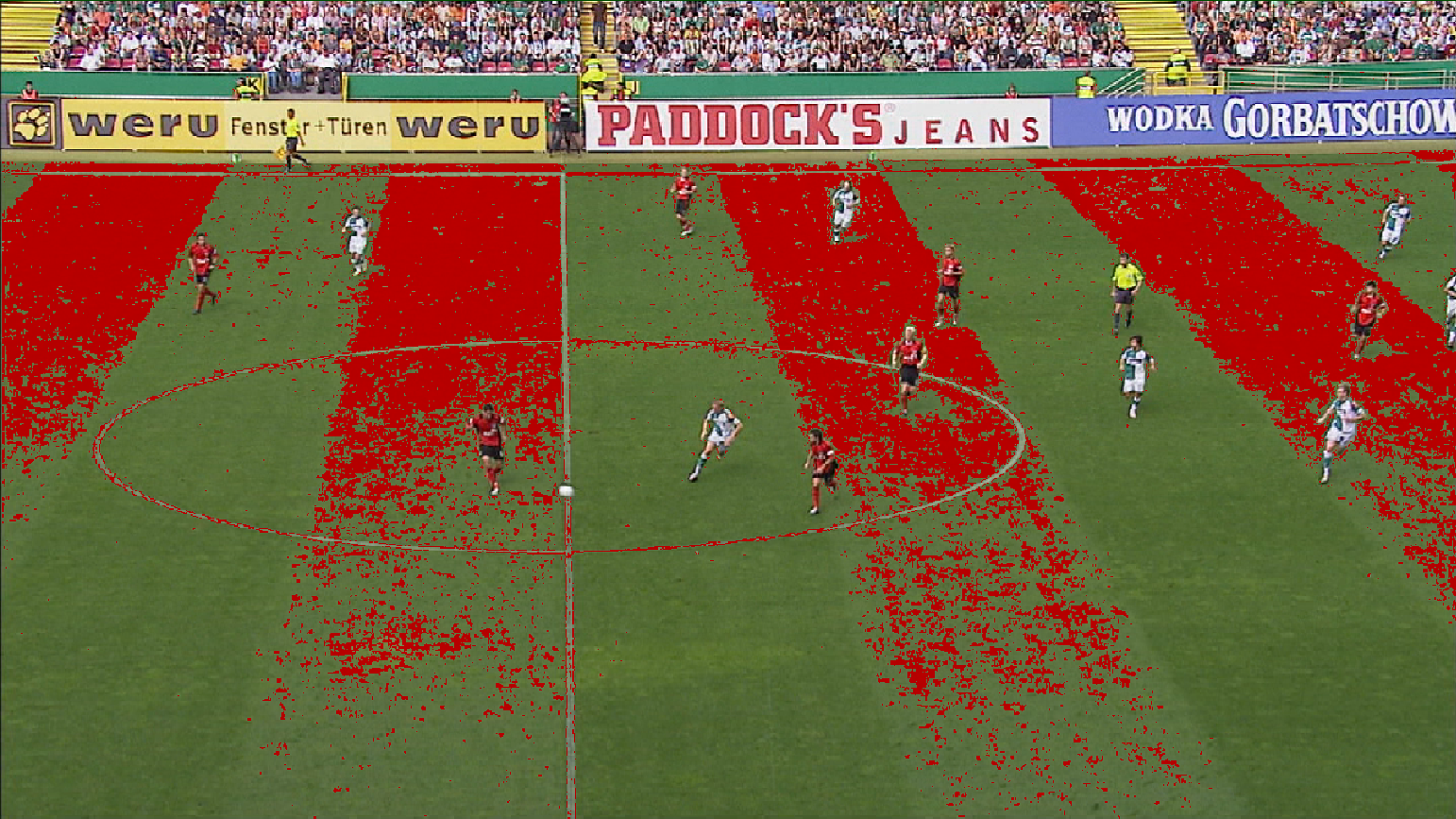
Adjust the Keyer so that the graphics will only be drawn on the white area and appear behind objects that are red.
Press End Pick when finished.
Press Reset to return to the default settings.
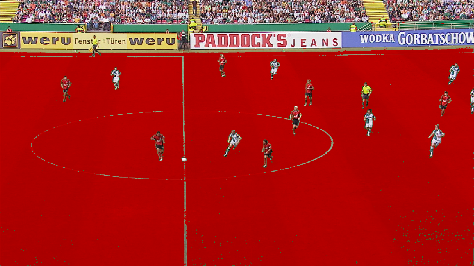
Edit Segment Keyer
Select and hold the active Keyer to display a list of Keyers.
Select the “gear” icon at the bottom of the list.
The Keyer Editor dialog is displayed.
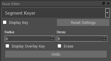
Display Key View and adjust the Keyer so that the graphics will only be drawn on the white area and appear behind objects that are black.
Radius/Decay Adjust the size of the Pick tool
Drag the cursor across the video to select the Keyed area.
DisplayOverlayKey View and adjust the Keyer so that the graphics will only be drawn on the red area and appear behind objects that remain.
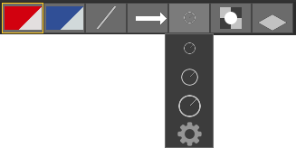
Palette
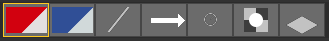
Use the Palette tools to set preferences for the graphics tools.
Palette tools include 2 colour combinations (Home and Away team), Thickness, Arrow Type, Size, Opacity and 2D/3D.
Select and hold the required Palette tool to change preferences.
You can also save customised palettes under a new name alongside other settings that can be customised (for example, you can name a palette the same as the home or away team) when you select to run Tactic with a league package
Colours
Select and hold the Colour Palette tool to change preferences.
A selection of team colours has been pre-defined.
To edit the Colour combinations, select the “gear” icon at the bottom of the list.
To change either the Primary or Secondary colour enter numeric values for RGB or use the Colour Picker.
Colour Picker
Add current colour definition to the colour palette.

Use the colour grabber to select colour from anywhere on screen.

Thickness
Select and hold the Thickness Palette tool to change preferences.
A selection of line thicknesses has been pre-defined.
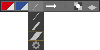
To edit the line Thickness, select the “gear” icon at the bottom of the list.
Arrow Type
Select and hold the Arrow Type Palette tool to change preferences.
A selection of Arrow Types has been pre-defined.
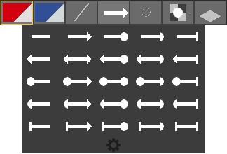
To edit the Arrow Type, select the “gear” icon at the bottom of the list.
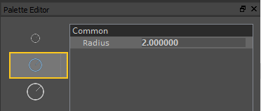
Size
Select and hold the Size Palette tool to change preferences.
A selection of Sizes has been pre-defined.
To edit the graphic Size, select the “gear” icon at the bottom of the list.
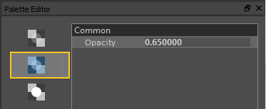
Opacity
Select and hold the Opacity Palette tool to change preferences.
A selection of graphic Opacity settings has been pre-defined.
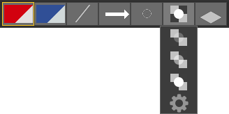
To edit the graphic Opacity, select the “gear” icon at the bottom of the list.
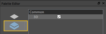
2D/3D
Select and hold the 2D/3D tool to change preferences.
Toggle between the 2D and 3D styles of certain graphic tools, or select the “gear” icon at the bottom of the list.
Create an Analysis sequence
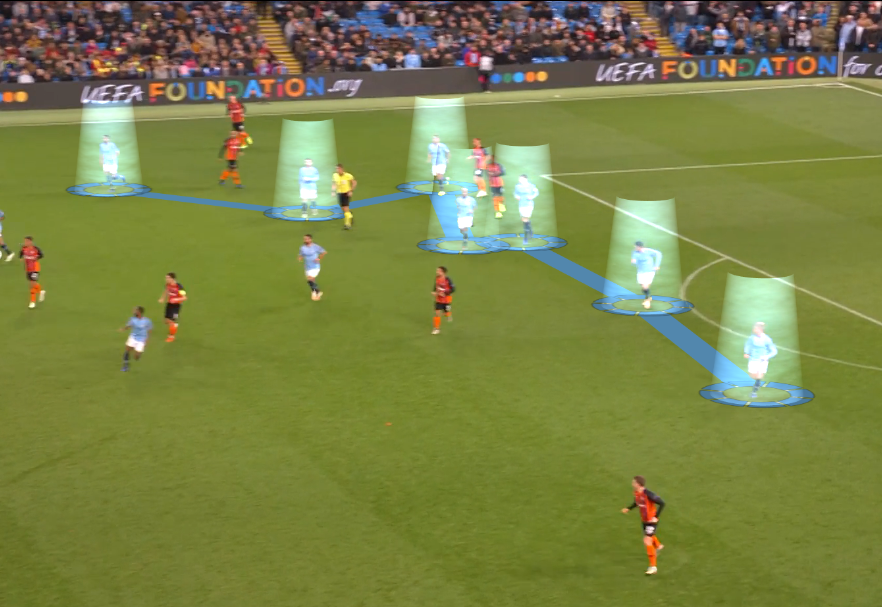
An Analysis sequence of a sporting event consists of a sequence of Graphics used to explain the game play.
An Analysis sequence is usually cropped from the full duration of the original video clip.
The Graphics may follow the game play using a technique called Keyframing or may appear tied to the pitch using a Tracked camera.
An Analysis sequence may contain manual or automatic pauses to enhance the explanation of the game play.
Before creating an Analysis sequence, it is necessary to:
- Load a video clip
- Choose a Camera
- Setup a Keyer (if required)
- Define the graphic colours and size etc using the Palette
Analysis sequences can be saved manually, or set to auto save, see “Auto Save” for details.
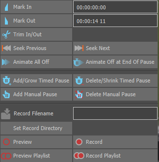
Mark In / Mark Out
Select Show Additional Analysis Tools at the end of the VT Controls toolbar.

(Select Show Additional Analysis Tools again to toggle the menu display on/off)
Either drag the vertical line on the Seek Bar to the desired video clip position or use the VT Controls to Play/Advance/Rewind the video clip and pause at the timecode a few seconds before the Analysis sequence will begin.
Select Mark In

Either drag the vertical line on the Seek Bar to the desired video clip position or use the VT Controls to Play/Advance/Rewind the video clip and pause at the timecode a few seconds after the Analysis sequence will end. The Mark Out should not be the very last frame of the video clip.
Select Mark Out

The total duration of the video clip displayed on the Seek Bar now represents the time period specified between Mark In and Mark Out.
Add Graphic(s)
Either drag the vertical line on the Seek Bar to the desired video clip position or use the VT Controls to Play/Advance/Rewind the video clip and pause the video clip at the timecode where a Graphic is to be added.
Select a Graphic from the menu.
Place the Graphic(s) on the video clip.
The “In” timecode of a Graphic(s) in an Analysis sequence is marked on the Seek Bar as a thin green vertical line(s).

Once analysis Graphic(s) have been added, navigate the Seek Bar using

Add Multiselect Graphics
Holding the shift key whilst selecting graphics from the palette will allow you to add multiple graphics simultaneously.
In this case, each click will add all the selected graphics together at the same time. Graphics such as lines and arrows will be linked, with each click adding another set of linked graphics.
Add or Delete a Pause
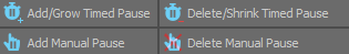
A Manual Pause will require the user to select Play to restart the video clip
A Timed Pause waits for a predefined time before automatically restarting the video clip. The duration of a Timed Pause is specified in the Analysis Options.
Manual Pause
Add a Manual Pause using

A Manual Pause is added to the Seek Bar.

Delete a Manual Pause using

Timed Pause
Add a Timed Pause using

or the dedicated button in the VT Bar.
A Timed Pause is added to the Seek Bar.

Reduce (or remove) a Timed Pause using

Adjust Pause
Adjust a Pause by dragging the end point on the Seek Bar using the “Left Mouse Button”.

Remove Graphic(s)
To remove a Graphic after either a Manual or Timed Pause navigate to the end of the Pause on the Seek Bar using

and at the end of the Pause use

Or to remove all Graphic(s) at the same time

The “In” timecode of Graphic(s) in an Analysis sequence is marked on the Seek Bar as a thin green vertical line(s).
The “Out” timecode of Graphic(s) in an Analysis sequence is marked on the Seek Bar as a thin red vertical line(s).

Preview
Playback the Analysis Sequence using

This will begin at Mark In, display the Graphic, Pause, remove the Graphic and continue to Mark Out.
Save Analysis
Save the Analysis sequence using
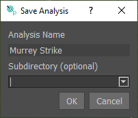
There are 2 modes of behaviour of the Save Analysis feature:
- Save Analysis button and CTRL+ SHIFT + S act as a “Save As”:
User is prompted for a filename. If the filename is already used, a warning window opens to ask confirmation for overwriting.
If no analysis has been saved or loaded since loading a clip, the name of the clip is suggested by default.
If an analysis has been saved or loaded since loading a clip, the name of the latest saved or loaded analysis is suggested by default.
If no clip or analysis has been loaded yet, no suggestion is made, the box is empty.
Analysis view has an expanded tooltip, allowing the full name of the file and modification date to be seen.
You can save analysis files into a subdirectory. These subdirectories will appear on the analysis list as folders that you can browse into, similar to clips
- CTRL+ S acts as a ‘Save’:
If an analysis has been saved or loaded since loading a clip, it is overwritten immediately.
If no analysis has been saved or loaded since loading a clip, it acts as a ‘Save As’ (see above).
Auto Save
By default, Tactic is set to automatically saves the current state of the clip (Key, tracking etc) along with analysis files. When enabled, Tactic will automatically reload the last saved state of the analysis, which will be highlighted with a red box..
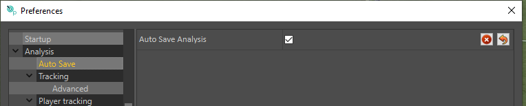
When playing out analysis files directly from Tactic, it is recommended that this feature is turned off.
The AutoSave directory is the same as the Analysis folder, for example:
RTSW/TacticPro/Football/AutoSave
Clear Analysis
It deletes all graphics in the current analysis sequence and reloads the current clip.
Note that the Mark In / Mark Out Timecodes and Tracking Data are preserved when re-loading the clip.

Load Analysis
Click on the Analysis tab and select the analysis from the browser.
If the clip used in the analysis is missing, if it has been or removed, then the following message will appear:
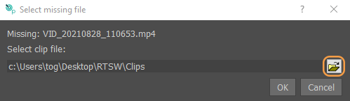
Clicking on the browse button will open an explorer window allowing you to search for and select the missing clip.
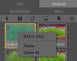
Delete Analysis
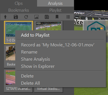
Select the Analysis, press the “Right Mouse Button” then Delete.
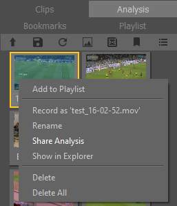
Share Analysis
The share analysis function allows you to export all of the elements of the analysis file (Clip, Analysis file,Thumbnail etc) to a single folder to be easily copied to another Tactic device.
Right click on the Analysis you wish to share and select “Share Analysis”
At the resulting pop up, click the browse button to select where you wish to export the analysis:
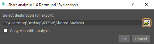
After clicking OK, a folder with the same name of the analysis will be created in the selected destination. To use the Analysis on another Tactic device, copy this folder to the analysis folder of the destination device, usually “C:UserstogDesktopRTSWTacticPro*******Analysis” (“*******” being the name of your current project folder/Sports package.
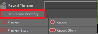
Record Analysis (Create a Layoff)
To Produce a movie file of the analysis sequence, select Show Additional Analysis Tools at the end of the VT Controls toolbar.
Then specify a Record Filename
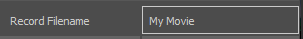
Then Record the Analysis sequence using

The movie file will be saved in the folder specified in Layoff options and in the format and quality specified in Layoff Movie format.
The layoff directory can be quickly changed by clicking on “Set Record Directory” in the Menu.
Record Analyses with right click
It is also possible to record an analysis or multiple analyses with a right mouse click. To record a single analysis, right click and choose “Record as”. To record multiple analyses, select them by holding down CTRL whilst and left mouse click. Then right click on one of the selected analyses thumbnails.
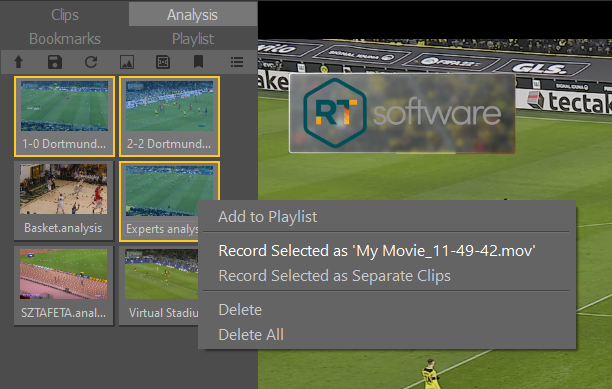
You can now choose to record them all as one continuous clip with “Record Selected”, the will be given the same prefix as defined in the record filename entry (see above).
Alternatively with “Record as Separate Clips”, a different clip will be made for each of the analyses with the same prefix, but a different time stamped suffix.
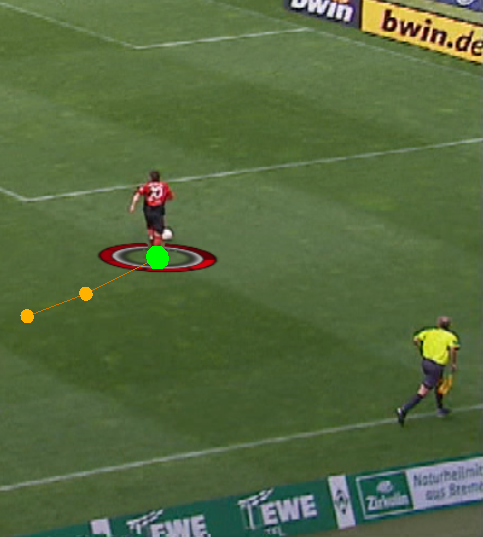
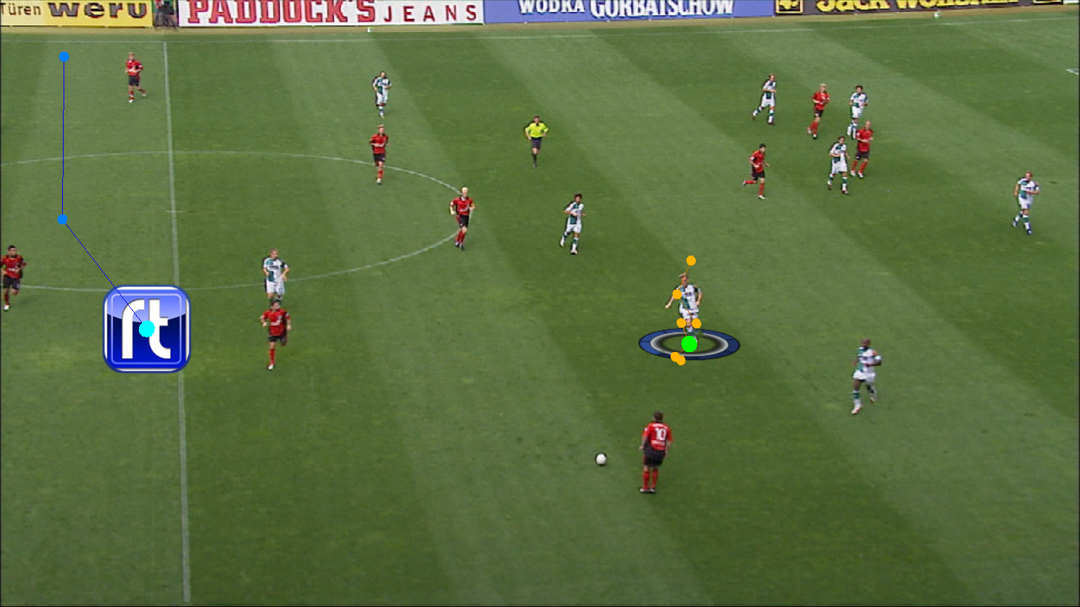
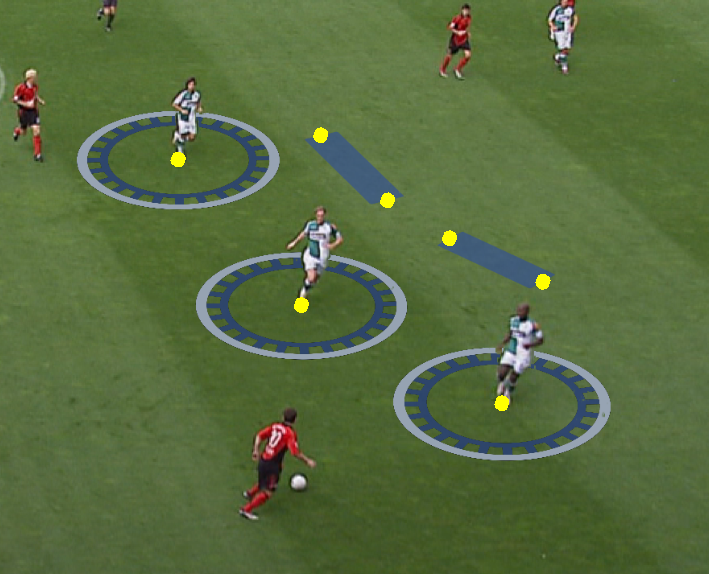
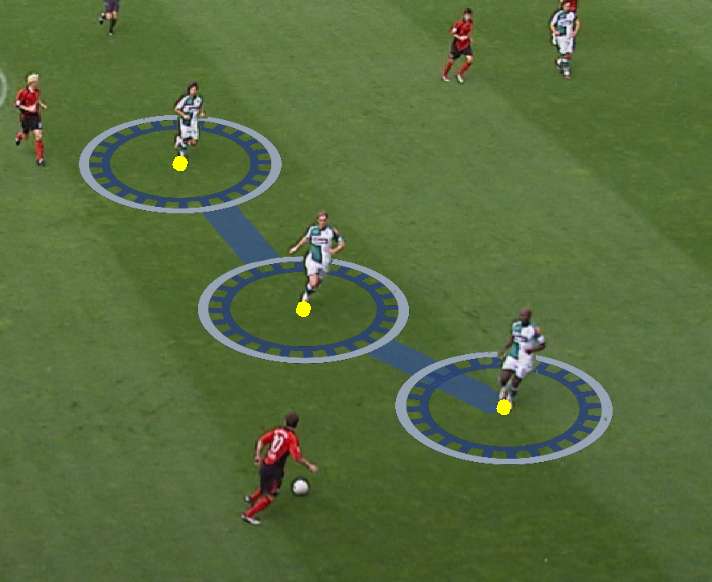
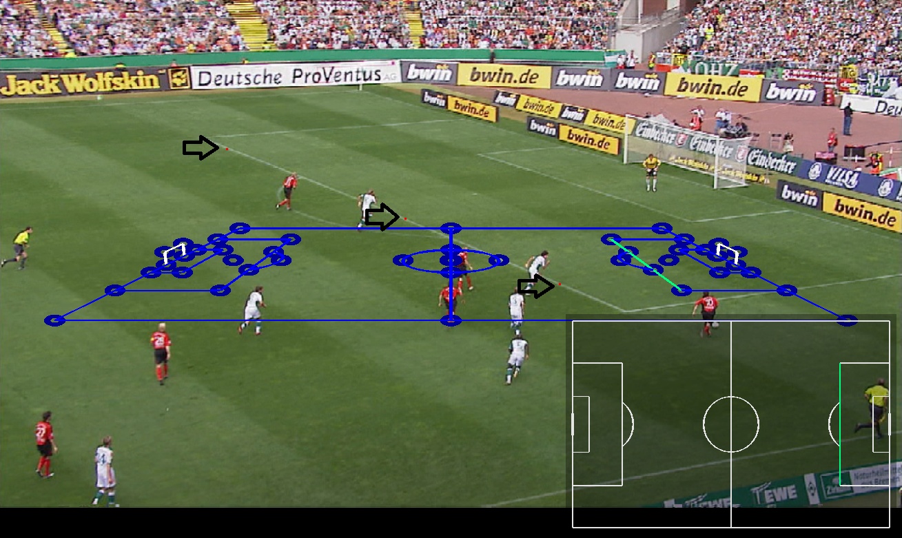
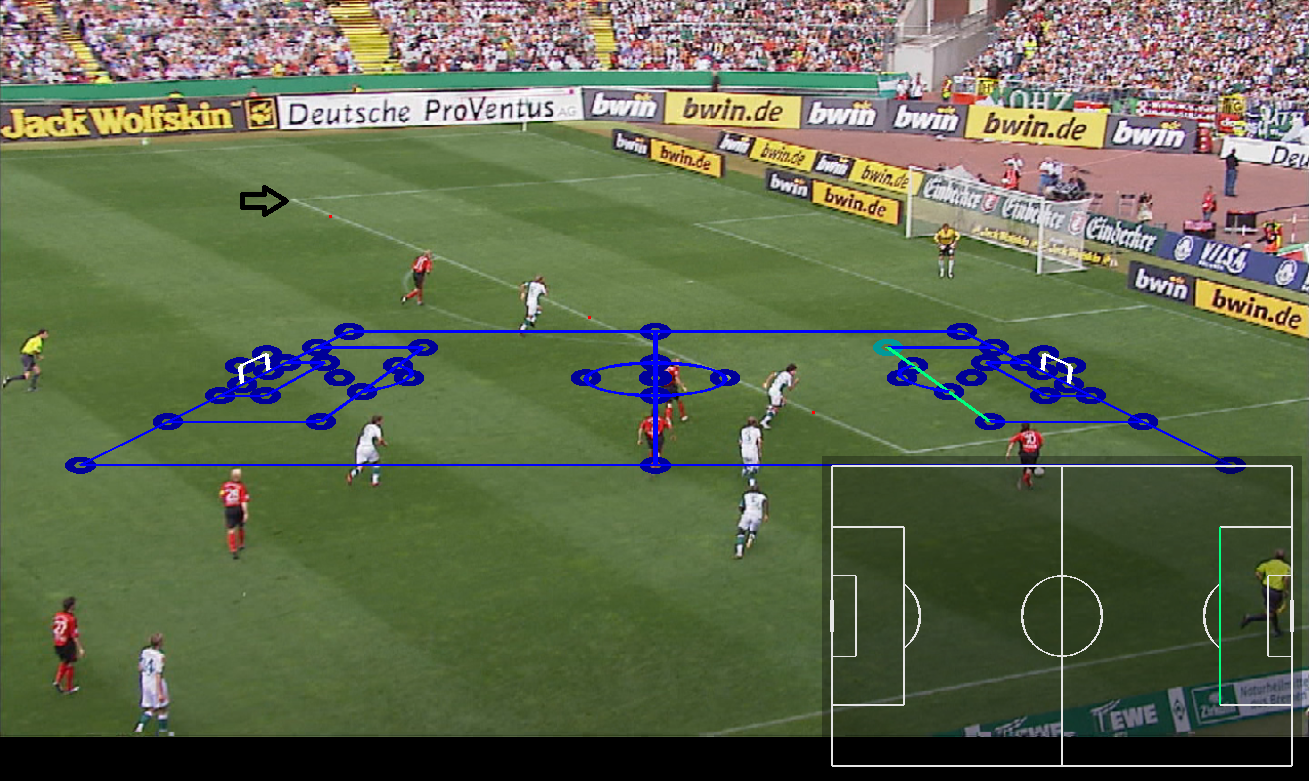
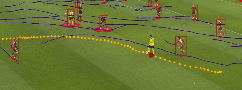
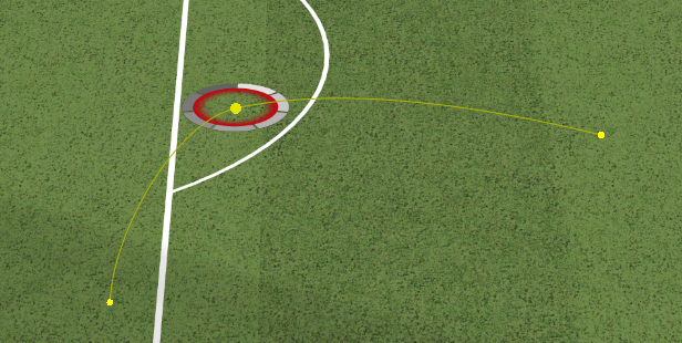
Motion Paths
Graphics can move and follow the game play as the video clip plays using a feature called “Motion Paths”.
All graphics can follow a Motion Path.
Multiple Graphics can be used and follow unique Motion Paths at the same time in the same Analysis sequence.
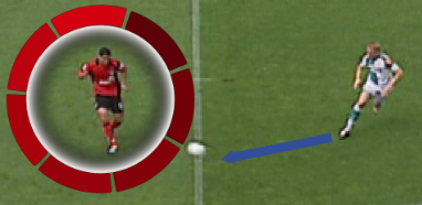
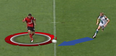
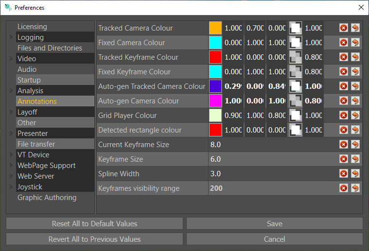
Motion Paths for Tracked graphics are Green, and Motion paths for non-Tracked graphics are Blue.
NOTE: These colours may be changed in the user preferences – Annotations
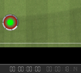
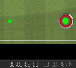
Add Graphic(s) to the video clip at the start of the chosen section of play and enable Motion Paths.
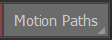
Once Motion Paths are enabled the icon turns green and dot(s) appear on the Graphic(s).
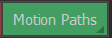
Select the dot and drag to adjust the position of the Graphic(s) (if necessary).
Either drag the vertical line on the Seek Bar or use the VT Controls to advance the video clip a few frames.
Select the dot and drag to adjust the position of the Graphic(s) (if necessary).
Continue to advance the video clip a few frames at a time and adjust the position of the Graphic.
At the end of the Analysis sequence insert a Pause if required and Remove Graphic(s).
The In and Out timecodes for the Graphic(s) and Pause are displayed on the Seek Bar.

Select Preview to review the Analysis sequence, Record and Save as required.
Edit a Motion Path
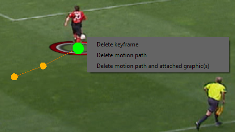
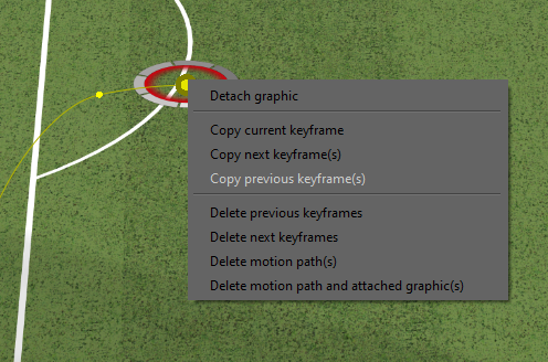
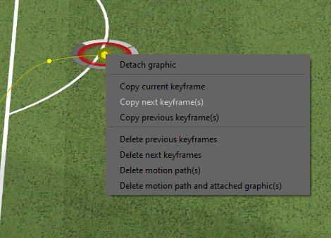
To edit a Motion Path, left click on the point of interest and drag it.
Delete a Motion Path
To delete a Motion Path or part of a Keyframe sequence, press the “Right Mouse Button” on the Motion Path.
Visible Motion Path(s)
To make editing easier it is possible to display ONLY the Motion Path(s) active at the current Time Code of the video clip.
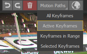
- All Keyframes: All keyframes in the clip
- Active Keyframes: All active splines in the video
- Keyframes visibility range: Before and after what was set in the settings (see below)
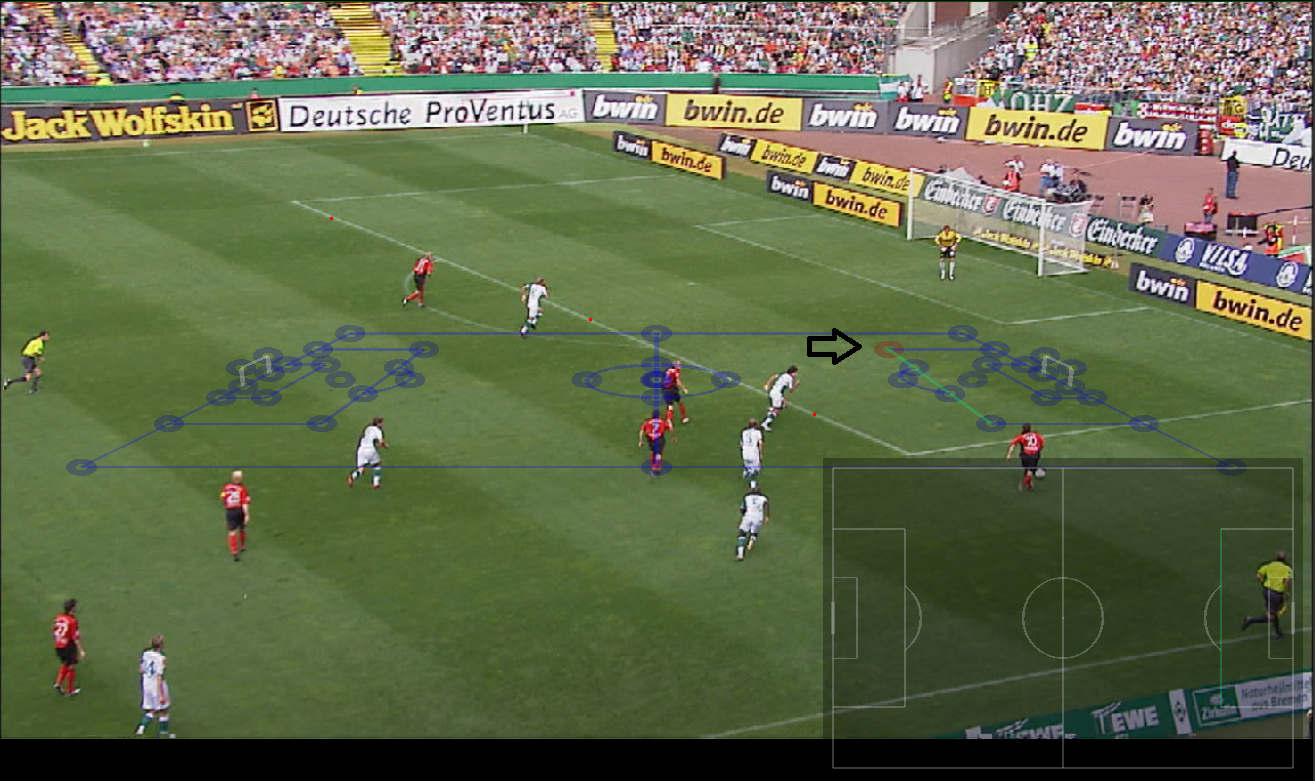
Tracking
Graphics can be “tied to the pitch” as the video clip plays using a technique called “Tracking”.
Not all graphics are suitable for use with a Tracked camera.
Multiple Graphics can be used and Tracked at the same time in the same Analysis sequence.
Enable Tracking

Once Tracking is enabled the Tracked button turns green.

By default, Motion Paths for Tracked graphics are Yellow, Motion paths for non-Tracked graphics are Blue, although these colours can be changed in the preferences menu under “Analysis/Annotations”.
You can mix Tacked and non-Tracked graphics by setting Tracked on or off before placing the required graphic.
Tracked means the next graphic placed will be using the tracking computation.
If Tracked is off the graphic will be untracked.
Note that this does not mean the tracking calculation is lost or needs to be redone.
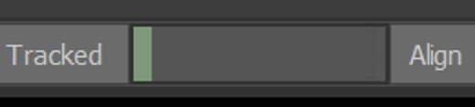
Once the Tracking data is calculated, a coloured line appears at the base of the Seek Bar.

Add Graphic(s) to the video clip at the start of the chosen section of play.
Either drag the thick red line on the Seek Bar or use the VT Controls to advance the video clip a few frames.
At the end of the Analysis sequence insert a Pause if required and Remove Graphic(s).
The In and Out timecodes for the Graphic(s) and Pause are displayed on the Seek Bar.

Select Preview to review the Analysis sequence, Record and Save as required.
Adjusting Tracking Regions
Select the “gear” icon beneath Auto Track to change the Tracking settings.

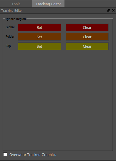
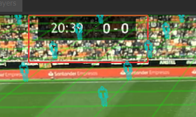
In certain circumstances it may be necessary to define a region of the video to ignore for the purposes of Tracking, for example, a scoreboard or league/TV channel logo.
Click on “Ignore Region” and draw a rectangle/square around the area you want to ignore, a red shape will form and that area will be ignored for tracking.
If you want to adjust the ignored area (enlarge the ignored region for instance), draw a bigger rectangle/square using the right-click mouse button, the new shape will be green and will erase the previous red shape.
Drawing a box inside the ignore region with the right click mouse button will draw a region that is not ignored.
Ignore regions can be set to be “Global”, so they are persistent and always there regardless of which clip is being used. Per “Folder” so they are used on all clips in the current folder or “Clip” so that they are unique to this clip.
Multiple types of regions can be added, so clip can use its own region and also the global region for example.#
Region boxes are coloured as follows:
Global: Red/Blue
Folder: Orange/Cyan
Clip: Yellow/Green
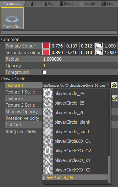
Edit a Graphic
The colour, thickness, style, size and opacity of many Graphics are controlled by the Palette.
These, and additional parameters of the chosen Graphic can be modified once the Graphic has been added to the video clip.
The speed of on/off animations, and with certain graphics the style of on/off animations, can also be modified.
Navigate using the thick red line on the Seek Bar to the desired video clip position or use the VT Controls so that the chosen Graphic is visible.
Or navigate to the chosen Graphic using
On/Off animations
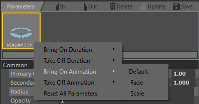
To modify graphic on/off animations, select the graphic that you wish to modify and right click on its icon above the parameters menu
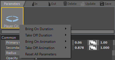
The Bring On Duration and Take Off Duration (if the graphic has an out point) can be selected from a choice of preset speeds.
.
For some graphics (Lines, Circles and regions), the animation style can also be selected. The choices offered will depend on the type of graphic, the image below shows the options available for circles.
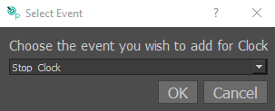
Graphic events
Some Graphics, such as clocks can have additional events that can be inserted alongside the traditional on/off events. Graphics that have this capability will show the “Graphic Event” bar in the parameter editor when selected.

Clicking on the “+”sign will offer a prompt allowing you to add new graphic events at the current timeline position.
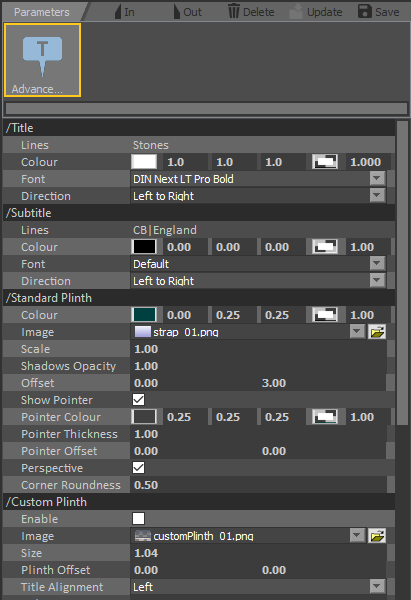
Parameters
Select the Graphic on the video clip.
The parameters of the chosen graphic will be displayed.
Adjust the colour, thickness, style, size and opacity etc.. as required.
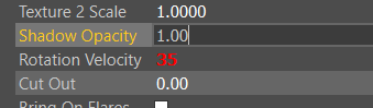
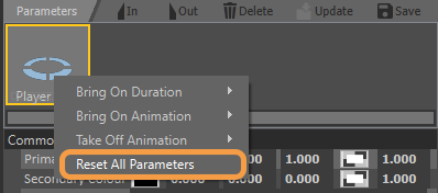
When you edit a parameter value, the edited field will turn red to indicate that it has been edited.
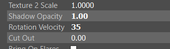
When subsequently using the same graphic with the edited parameter, the parameter field will be in bold to indicate that it is no longer the default value.
This value can be reset to default by right clicking on the parameters heading and choosing “Reset Value”.
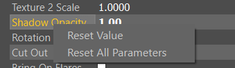
You can also choose to “Reset All Parameters”, which can also be selected with a right click on the graphic tool as in image below. This will reset all the graphic parameters back to their default value, or in the case of the parameters that are defined in the Palette, the values defined in the palette.
Set In/Out Timecode
The In timecode for Graphic(s) are initially set at the timecode when the Graphic(s) are added to the video clip. See Add Graphic(s).
The Out timecodes for Graphic(s) are set individually or all at the same time. See Remove Graphic(s).
Adjust the In and/or Out timecode by navigating using the red line on the Seek Bar to the desired video clip position or use the VT Controls and use
Delete Graphic
Delete the current Graphic from the Analysis sequence using

Create Style
Change the of the current Graphic and Save this as a new style using

Choose a name and an icon to represent the new style.
To allow the new Graphic to share colour, thickness, style, size and opacity from the Palette, enable “Use Tool Palettes”.
This will be added to the Composite Styles tab on the Graphic menu.
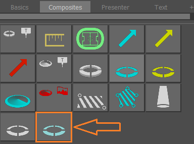
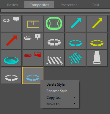
Delete Style
Select the Graphic with the “Right Mouse Button” to delete it from the Composite Styles menu
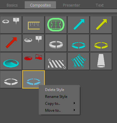
Rename Style
Select the Graphic with the “Right Mouse Button” to rename it from the Composite Styles menu
Add Pages for Composite Styles
Select and Drag the Graphic with the “Left Mouse Button” and place it on the + sign
This will move the selected Graphic to a new Page
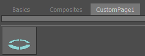
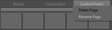
To Delete a Page, select the Page with the “Right Mouse Button”
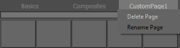
To Rename a Page, select the Page with the “Right Mouse Button”
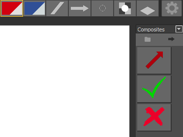
Composite Graphics
Basic Graphic styles can be combined together to build more complex, Composite Graphics.
Add Basic Graphic(s)
Add the Basic Graphic(s) as required to build the new Composite Graphic.
Enable Motion Paths
Once Motion Paths are enabled the icon turns green and dot(s) appear on the Graphic(s).
Select and Drag the dots to combine the Graphic(s).
When complete, disable Motion Paths.
The Composite Style Graphic may now be used with Motion Paths in the same way as a Basic Style Graphic.
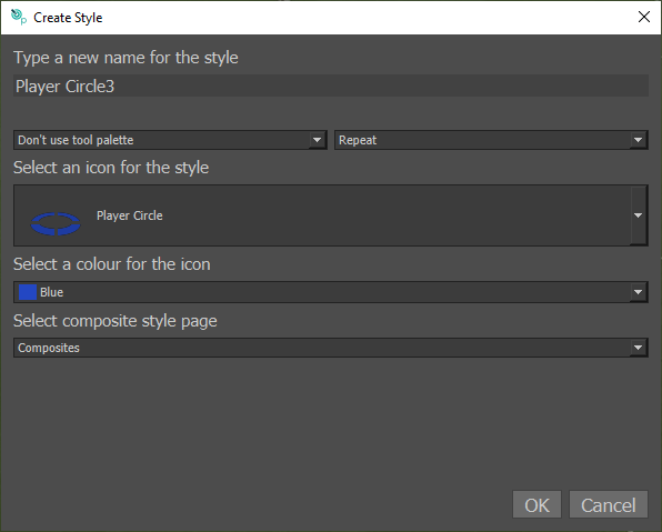
Save Composite Graphic
Save as a new Composite Style using

Choose a name and an icon to represent the new Composite Style.
This will be added to the Composites tab on the Graphic menu.
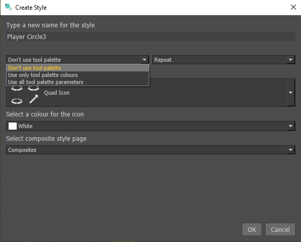
There are three options which determine how the style of the saved graphic will appear when used. “Don’t use tool palette” is the default, in this case the graphic will always appear in the state (Colour, line style etc.) in which it is saved regardless of the current tool palette selection. If “Use only tool palette colours” is selected, the graphic will use the colour that is currently selected in the tool palette but will ignore other palette options such as line style and will use the style in which the graphic was saved. “Use all tool palette parameters” will use all parameters in the tool palette including line styles ignoring the colour and style that were saved with the graphic.

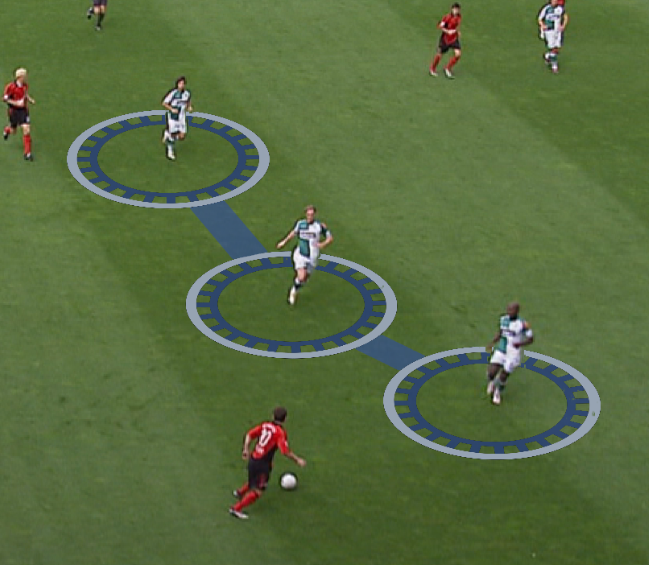
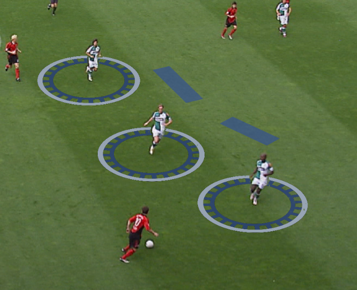
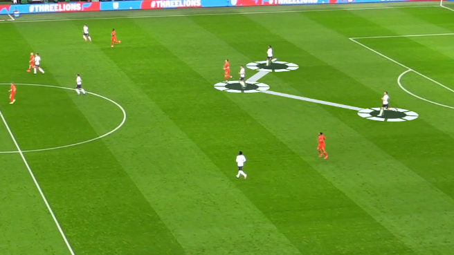
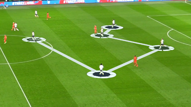
There are multiple options for how the graphic will behave on the pull down menu, “Run Once” means that you only use the graphic once before the tool becomes inactive, “Repeat” allows you to carry on adding new instances of the graphic one after the other. “Multiclick” allows you to keep growing the graphic, in the case of a circle and connecting line, each time you click a new player, a new circle and line is added, as below:
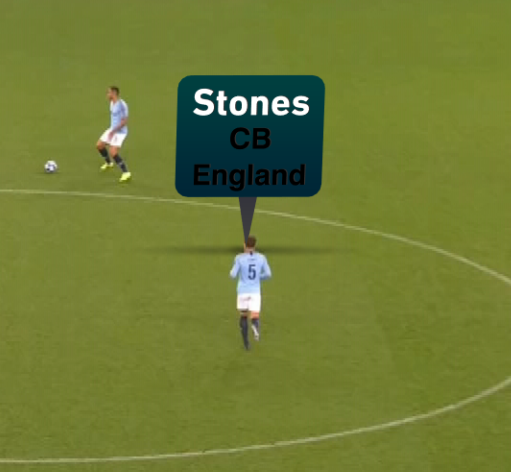
Text Entry Tool
The “Text” tool allows quick selection of text from “packages” of data.
It provide player names, positions, numbers, etc as a spreadsheet
The text data is retrieved from “Comma Separated Values” file (.csv) that should be placed into the League package Text folder
Text templates allow names, numbers, etc. from a “package” to be quickly applied to a graphic.
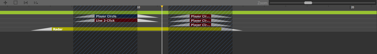
Timeline
Graphics added to the analysis will appear in the timeline.
Adjust the scale of the timeline

Timeline tools
Adjust and manipulate graphic properties within the timeline.
The “in” timecode, “out” timecode and overall position in the timeline can be adjusted by dragging the item in the timeline using the Left Mouse Button.

in “timecode”

out “timecode”
position
Select graphic(s) in the timeline using the Left Mouse Button and draw a box around multiple graphics in the timeline and subsequently edit together. Or you can hold shift, then select the first and last graphic you wish to select. Alternatively you may hold control and select each graphic individually.
Group selected graphics together
Ungroup selected graphics
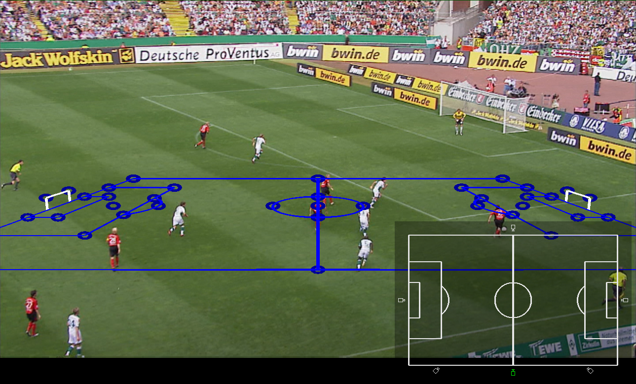
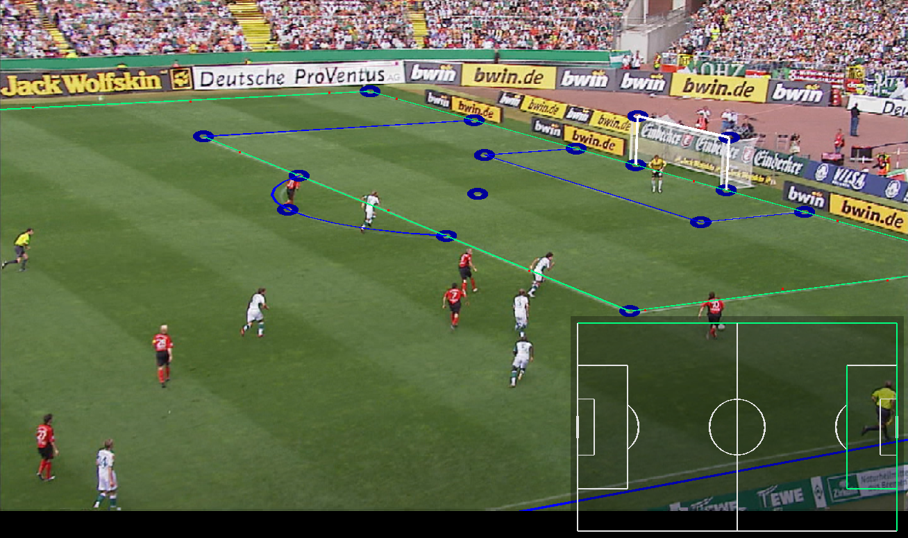
Pitch Calibrate
If you are working on a sport that uses lines on the playing surface such as Football (Soccer), Rugby or even Ice hockey, you may be able to use these lines to calibrate your camera. After calibration, your camera will be perfectly aligned with the source camera. Subsequently, as well as your graphics being in perfect perspective, you will also be able to use metric graphics to measure distance or speed and place an offside line with one click.
The icons for Metric graphics are displayed in the tool palette in orange colour, as below:
Automatic Pitch Calibration
You can calibrate a camera either manually, or if you are working on Football (Soccer), AFL or NFL you may be able to calibrate automatically. In either case, you must first ensure that you are using the correct line model and parameter set.
The Standard installation of Tactic Pro includes the line model for Football. AFL and NFL models must be installed separately if working with those sports. Go to https://rtsw.co.uk/software-downloads/#tab-2, and scroll down to find the pitch model downloads for the appropriate sport. Click on the button to start which will start downloading a .zip file. When the download is complete, run the .exe file within the .zip folder and go through the standard installation process. On completion, re-start Tactic Pro and you will find the Automatic Pitch Calibration button available when selecting the relevant sport on startup. The Automatic Pitch Calibration button is not available in other sport projects.
Select Calibration from the Edit Camera dialog.
Or click on the gear button underneath the Pitch Calibration button in the toolbar (long hold on the Pitch Calibration button.)

Select the Pitch Model, in this case Football.
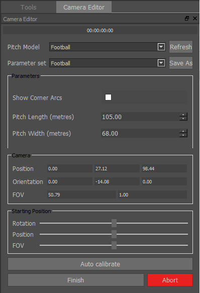
If your clip is from a game that is in non standard dimensions, changing the parameters here to match the actual pitch dimensions will result in more accurate metrics. You can save your new dimensions as a parameter set if required for faster recall later.
You can now press Auto Calibrated from this menu.
Alternatively, if you know that the correct Pitch Model and parameter set is already selected, you do not need to enter the camera editor menu, simply click the Pitch Calibration button in the toolbar once.

If the auto calibration is successful, you will see the pitch model appearing as blue lines overlaid on the lines in the playing surface as below:
The blue lines will fade out after a few seconds, although if you wish to have the model permanently displayed, click on the model button in the top bar (Circled above).
You can now use accurate metric graphics on this frame, or Auto Track from this point.
Manual Pitch Calibration
If you find that the auto calibration is not successful, you may need to perform a manual calibration. To do this, once again enter the camera editor menu and click “Calibration”
Select the Pitch Model if not already selected
.
Check the Pitch dimensions and Save as a Parameter set if required.
A Pitch model will be displayed …
Select the Camera position

Using the “Left Mouse Button” select a line or circle on the pitch model…
Using the “Left Mouse Button” select 1 or more points on the pitch using and finish with the “Right Mouse Button”. The line will display Green once calibrated.
Using the “Left Mouse Button” select a corner point on the pitch model…
Using the “Left Mouse Button” select the point on the pitch. The point will display Green once calibrated.
Repeat this for several lines, circles and corner points on the pitch until a good alignment is achieved.
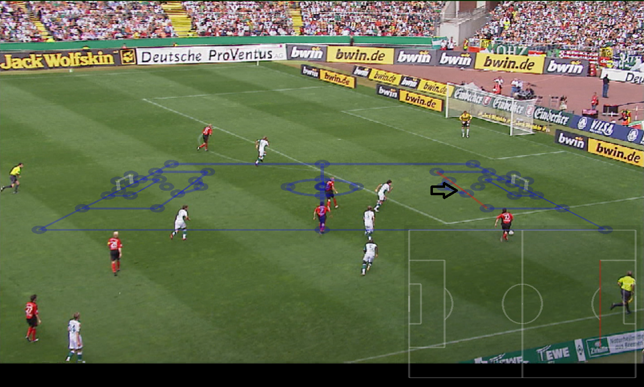
Select Finish to complete the calibration…
The Render Grid will now be correctly aligned to the pitch…
Toggle the Grid display on/off
You can calibrate multiple clips at the same time.
You can now calibrate channels 1 and 2 at the same time. Pressing finish will compute positions for both cameras.
Pitch calibration Custom Markers
When calibrating multiple clips at the same time, you will now see there are some additional crosses on the pitch model.

These allow you to add extra points of data to the calibration that you can see in both clips, but are not in the pitch model.
For example, a player’s foot could be used as an extra piece of information.
Click a colour cross, and click where the point is in the first camera shot.
Move to the second video channel, click the same coloured cross, and click where the point is in the second camera shot.
You can delete crosses by clicking them in the video window, and middle-mouse-clicking (same as to remove lines)
These are useful for getting a more accurate calibration for camera morph.
New crosshair cursor, allows more accurate clicking.
Pitch calibration Key Frames
When working with a clip with lots of fast panning, it is possible the calibration may dis-alsign, to resolve this perform a regular pitch calibration at the start of the clip mark in. Then using the timeline, move to a period after the pan or when the calibration has lost alignment and perform the calibration again by clicking on the blue pitch frame. This will automatically create a new calibration keyframe. More than two keyframes can be used if required.
When the pitch calibration window is open the Keyframe controls appear at the top of the window, between the keyer and player detect button. This allows you to select/deselect keyframes and jump to the next or previous keyframe.
Additional Pitch Markings
Each sport provides a number of parameters allowing customization of the pitch model. Some of these are optional to allow for improved calibrations beyond what is possible with just lines on the field, such as goal posts or standardised flag markings. However, most of the options determine important properties of the field you’re calibrating against. Pitch width and length are common in many sports, and these should be set as accurately as possible. Other options are for rule variations, such as singles versus doubles nets in Tennis. It is important that these options be set to match the field wherever possible.
Parameter Sets allow you to save and load a package of parameters for future use. For example, you could save different values of pitch width and length corresponding to different stadiums.
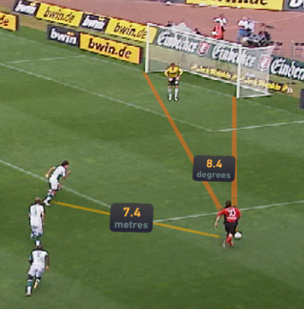
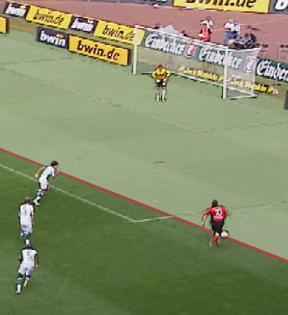
Once the pitch is correctly calibrated it is possible to measure angles, distance, speed and offside line using the graphics tools…
Default Camera Position
The calibration default view matches the common pitch centre high-and-wide view. However, some cameras might fail to calibrate if they are too far removed from that initial view, for example offside or behind goal cameras. In that case, before selecting any lines, use the Rotation, Position, and FOV sliders under Starting Position to adjust the initial perspective to be closer to that of the actual camera.
Advanced Tracking
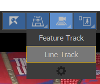
Line Tracking
Tactic provides two tracking modes. By default, Autotrack uses Feature Tracking, which searches for 2D features in the image to track the 3D camera. Line Tracking is an alternative technique that uses the lines on the pitch to track camera motion.
To enable line tracking for a calibrated camera, ideally a multi-pose camera, enter Edit Lists, right-click the desired camera, and select “Enable Line Tracking”.
Important: The Ultra tracking profile for line tracking is extremely computationally intensive, and may result in worse results for some clips. It is highly recommended to use at most the High tracking profile when Line Tracking.
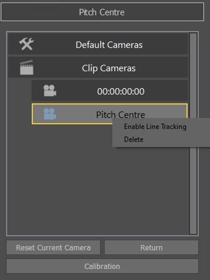
An automated calibration process will proceed in the background, and save to disk. The camera name will turn blue to indicate that Line Tracking is ready.

To use Line Tracking on a clip, click and hold the Autotrack button. A new menu appears allowing the selection of Feature Tracking or Line Tracking. Select Line Tracking to enable the clip.
Line Tracking depends on Keying being enabled. If Keying is disabled, attempting to use Autotrack will fall back on Feature Tracking. Keying should be configured correctly for better results. Click Autotrack to track the clip using Line Tracking. Each clip will remember whether it was last tracked with either Feature Tracking or Line Tracking.
You can limit autotrack to mark in/out regions and not track the rest of the file.
Limit Auto Track Region, currently under preferences->Analysis->Tracking->Advanced
You can add tracking barriers, commands to tracking to stop when hit without having to put down dummy graphics
Camera Re-Init
You may notice on starting a Line Tracking Autotrack that it takes a few seconds to start tracking. This is due to computing an initial camera state based on the pitch lines across the whole image. However, this process may fail with poorer quality clips, poor keying, or insufficient lines visible, and if so, tracking results will be unusable.
It is recommended that, before starting tracking, the user finds a frame that will re-init correctly. This re-init can be triggered manually by single-clicking the camera button in the toolbar with a Line Tracking-enabled camera selected.
From the desired starting frame that fails to re-init, seek in roughly half-second increments either before or after that point, and re-initting the camera until it succeeds, and start Autotrack from that frame.
Alternatively, if no frame succeeds satisfactorily, use Align to re-init manually on the desired frame, and then start Autotrack, which will skip the automatic re-init process.
Re-Tracking
Any tracked clip may be re-tracked by clicking Autotrack again. This will overwrite the previous track. However, any tracked graphics that were placed prior to re-tracking will maintain their original track, unless “Overwrite Tracked Graphics” is enabled in the Tracking gear menu.
Pitch/Grid Dropdown Menu:
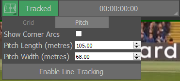
- Long-hold on the “Pitch” button.
- It allows selection between grid and pitch view for the visualisations.
- It allows line tracking to be enabled without doing it via the camera editor menu.
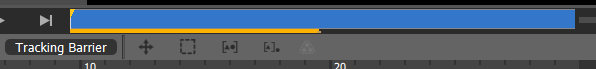
Tracking Barrier:
This feature allows you to set a stop point to auto-tracking, if for example you want to track a segment of the clip and not the entirety of it.
Scrub the clip until reaching the point you want the auto-tracking to stop and click on “Tracking Barrier”.
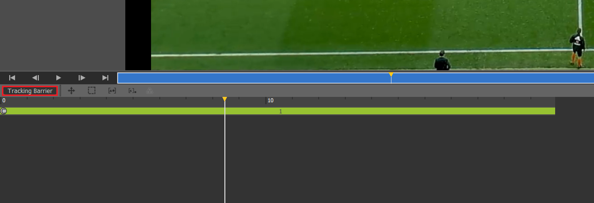
Once you click on the button, a marker will appear on the scrub bar
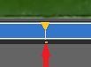
You can now rewind to the first frame of the clip and hit “Auto-Track”. You will notice that the tracking line stops at the designated point
Advanced Pitch Calibration
When you perform a pitch calibration, by default it creates a pseudo camera tied to the current timecode of the current clip. However, the computed camera position may be several decimetres off from the actual position. In general, this is fine for showing graphics on static shots, or tracking over a short term, but for tracking longer shots (such as one side of the pitch to another), or using line tracking, this can create notable artefacts. In addition, you may want to reuse a camera with another clip of the same game without recalibrating, or simply give a camera a unique name for future reference. Two related features solve both these problems.
Named cameras can be renamed and moved between user-created camera lists just like standard user-created cameras, but can be re-Aligned like calibrated (timecode) cameras. To create a named camera, when starting a calibration, select one of the camera icons around the pitch model
. These correspond to common camera positions like Pitch Centre, Offside, and Behind Goal. Notice this also updates the initial perspective.
Multi-pose cameras allow you to repeat the calibration at different points in a clip. The calibrations will be combined to refine the camera position, improving the accuracy of the results. Multi-pose cameras are always also named cameras. If you do not select a preset from the onscreen pitch model, the resulting camera is simply named “Camera”, but like standard (single-pose) named cameras, can be renamed later.
To create a multi-pose camera, after calibrating on the desired starting frame, simply seek the transport control to the desired next frame, and repeat the calibration process. Ideally, should the clip contents permit, this should be repeated for views to the left, centre, and right sides of the pitch, each at wider and tighter shots. If there are cuts in the clip, be sure to only calibrate on frames corresponding to the same physical camera. Click Finish as usual to complete and save the calibration. You’ll notice that the currently selected resulting camera now shows a name instead of timecode.
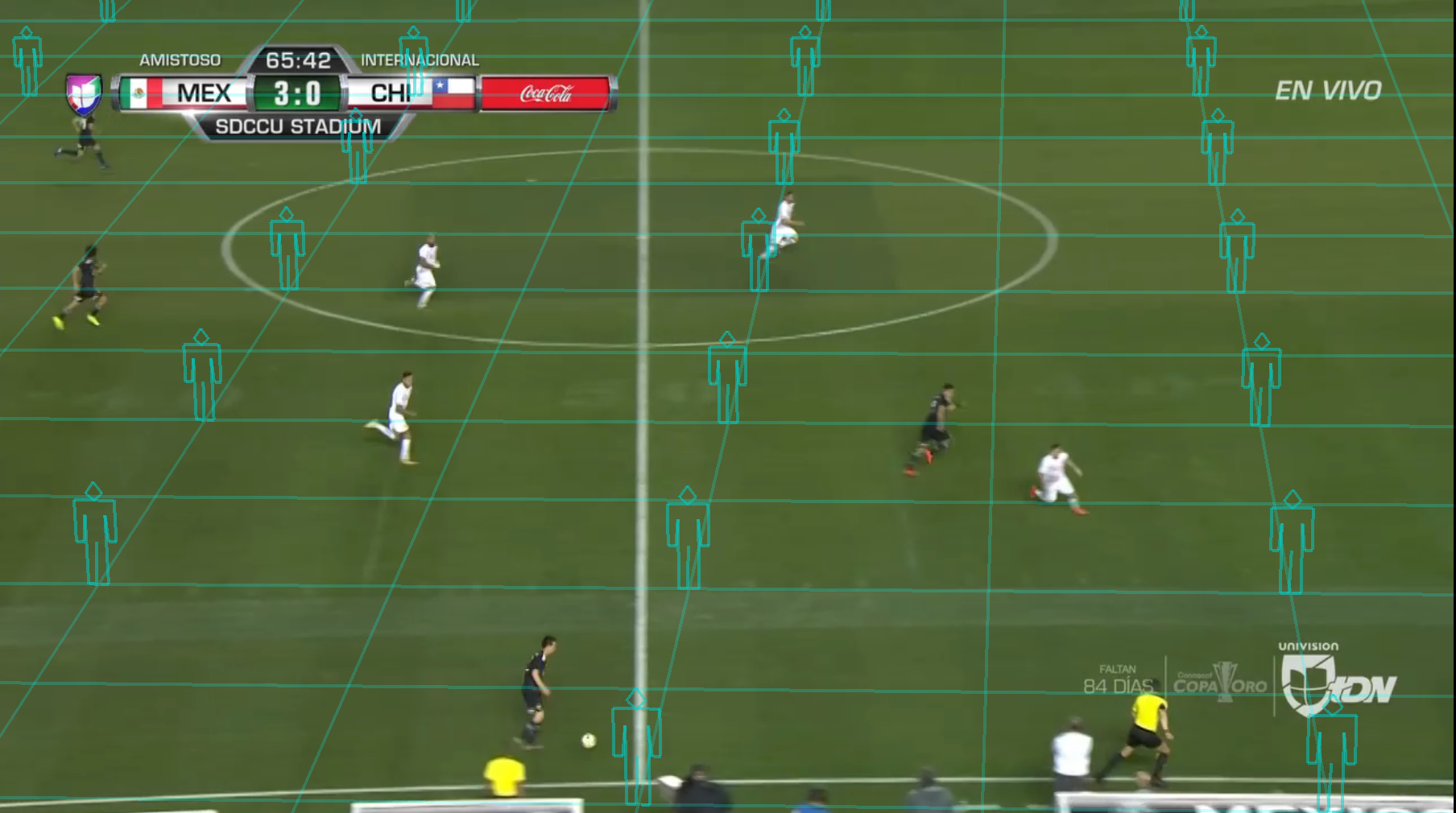
Player Detection
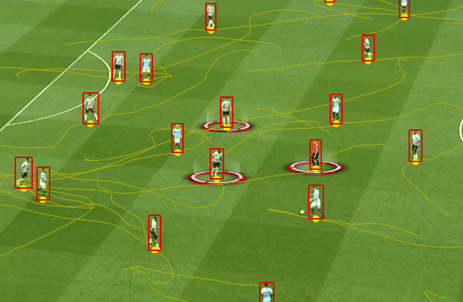
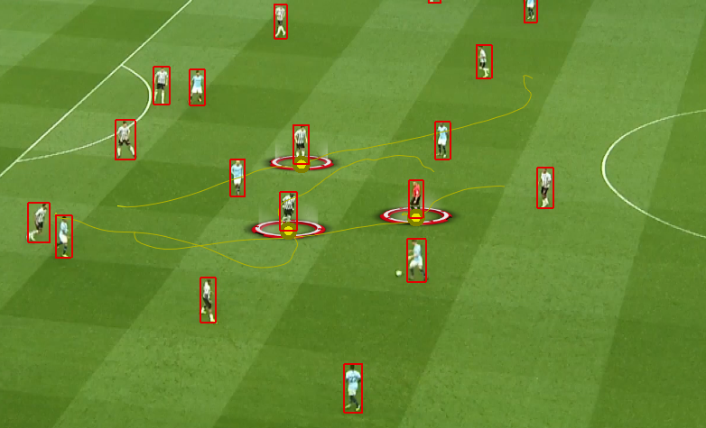
On supported platforms, Tactic can now automatically detect and track players on a number of sports. Different player detect models can be selected depending on sport which may give better results. See the Player Tracking section In Appendix A for more information.
Requirements
- On Windows, Player Detection only works with Nvidia GPUs. Maxwell or higher architecture is recommended.
- The Detect Player button should only appear on supported platforms.
- Ensure you have the “Player Detection” button on the interface. If not visible, player detection is not available.

- Load Clip
- Calibrate Clip/Autotrack
- Wait for the tracking to complete (not necessary but may be problematic on lower-end machines)
- Click “Player Detection”
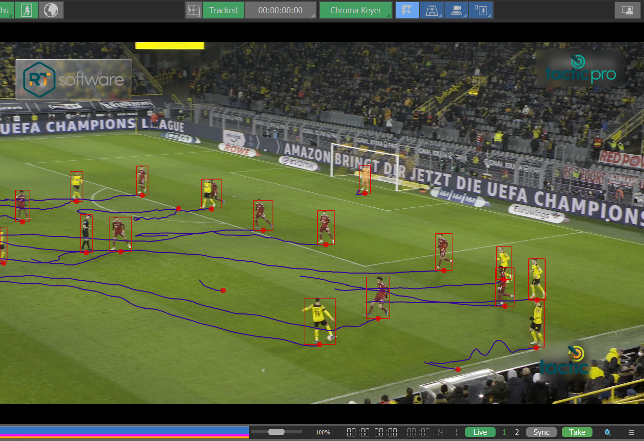
- Once enough of the clip has tracked, you can press Player Detection again to stop the player detection.
- Whilst the red rectangles are visible, you can click graphics onto them rather than the motion path on the players feet – this gives you a bigger target to hit and is slightly less fiddly.
- Turn red rectangles on and off by long-clicking the Detect Player button and pressing “Show Detections”
- Motion paths generated by Player Detect are different to motion paths created by hand – right now you can only edit them using certain commands (merge, swap, etc.)
- You cannot add extra points manually onto an auto-generated motion path right now.
- You can also right click on a motion path and select “Delete keyframes in between” to delete the keyframes between the selected items.
- New spline colour options available in Preferences to distinguish between auto-generated motion paths and user-created motion paths.
Show Selected Keyframes
You can select “Show Selected Keyframes” to highlight only selected keyframes. To do this first select another “All Keyframes”, then select multiple keyframes using the Shift key and select “Show selected keyframes”.
Then when you select “Show Selected Keyframes” you will only see those that are selected. This is useful when you have a high density of players and are only interested in some players.
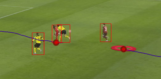
Merge Splines
Allows you to merge two splines together when a spline has been split in two (often the case if a player goes out of shot momentarily).
Select the two splines that you with to merge using Shift+click, and right-click-
>merge splines
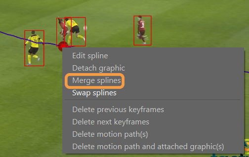
The splines will be merged into one
This work flow is useful for merging two motion paths together when the player detection has generated more than one motion path for a player. A common case of this is when a player goes off screen for a couple of seconds before the camera pans to follow them.
Swap Splines
Allows you to swap all keyframes after the current timecode in two different splines. Here are two splines.
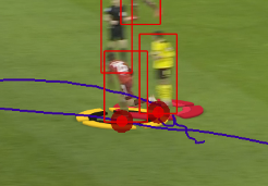
Shift-Click the two motion paths, right click and clip Swap Splines
The splines will now switch paths after the given timecode.
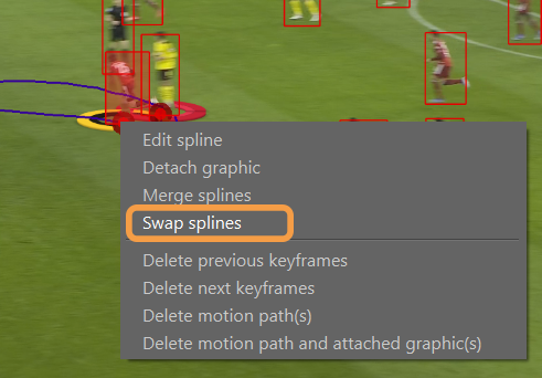
This is useful if player detect starts tracking the wrong player after two players have intersected on the screen.
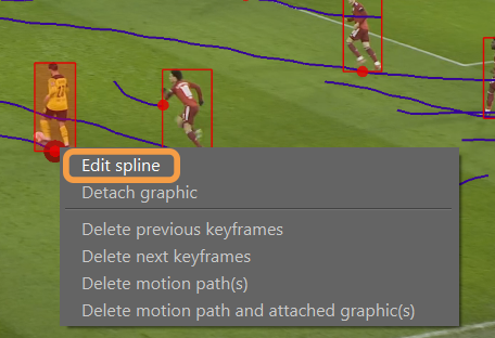
Edit Splines
Converts an auto generated spline (created by player detection) into an editable spline. This allows the operator to go in and extend it, or correct issues in the player detected track.
Detach Graphic
This allows you to remove a graphic from an existing motion path, allowing you to either keyframe it separately, or attach it to a different motion path.
Delete Previous Keyframes
Deletes all keyframes on the current motion path before the current timecode
Useful for quickly trimming a motion path to only have the data in it that you require.
Delete Next Keyframes
Deletes all keyframes on the current motion path after the current timecode.
Useful for quickly trimming a motion path to only have the data in it that you require.
Delete Keyframes between
Deletes all keyframes between two currently selected keyframes.
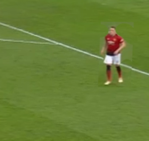
Player Drag with Player Cleanup
You can drag a player to a different location
- Use the “PlayerDrag” from the graphics menu
- Place it on the player you want do drag, a white cross should appear at the bottom
- Now click on another area of the pitch where you want the player to be dragged to
Player drag tool uses Artifical Inteligence (AI) to attempt to fill in the background (missing white lines etc). However, some manual clean up of the graphic may be required.
- Right-click on the graphic in the parameter editor and select “Cleanup”
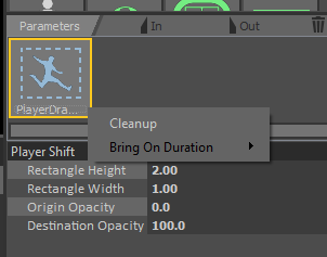
- This will open the player cleanup interface. This interface works very similarly to the camera morph and pitch cleanup interfaces, with the following additional changes:
- Setting the clone area is available with Ctrl + Left Mouse Click
- Holding down the Alt button allows you to zoom in with either Right Mouse+drag, or by using Mouse Wheel
- When zoomed in, holding down Alt + Left or Middle Mouse buttons and dragging around will pan the camera.
- Press [ to shrink the brush size and ] to enlarge the brush size on both Windows and OSX.
- Hold shift and [ or ] to soften or harden the brush on both Windows and OSX.
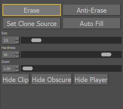
You can erase the dragged pitch lines alongside the player for example and clone lines to fill the gap created by the player gap using the Player Cleanup tool.
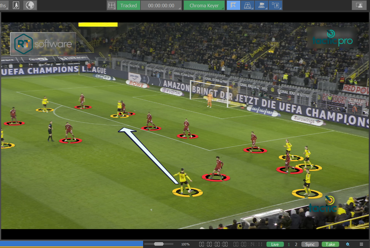
Virtual Stadium
The virtual stadium view is a graphic tool that can be used at any part of an analysis. Users may add graphics to a clip, then enter the virtual stadium to see a virtual view. If the camera is calibrated at that point, the virtual stadium camera’s position will mirror the clip camera position. The clip will still run in the background behind the virtual stadium, so pressing play (unless a pause has been inserted) will play the clip in the background.
If users wish to create an analysis entirely in the virtual stadium view with no clip in the background, they can use the “Create an analysis with no clip (black background) and a stadium graphic button” which will automatically enter the virtual stadium view. See “Using a black background”.”
Otherwise, enter the Stadium View using:

The virtual stadium becomes a graphic on the timeline that can have in/out points associated with it allowing the analysis to move between virtual stadium and the video view at any time in the analysis. Graphics added between the virtual stadium in/out points will appear as graphics in the virtual stadium.
Select Virtual Stadium Camera
The currently active Stadium Camera is displayed on the Toolbar.
Select and hold the active Stadium Camera to display a list of Cameras
The selection displayed is the default list of cameras, users can create new cameras with the “+” key and delete any cameras with the corresponding “-” key.
Select the required Stadium Camera from the list.
Edit Stadium Camera
Select and hold the active Stadium Camera to display a list of Camera presets.
Select the “gear” icon at the bottom of the list.
The Camera Editor dialogue is displayed.
Adjust the position of the camera presets using the slider bars (or place the cursor over the required slider bar and use the mouse wheel).
“Reset Current Camera” Resets to the installation defaults
“Edit Lists” Selects and Edist specific camera from the Camera List
Note The Camera Editor is only meant to be used to adjust/edit the Camera presets.
New Camera presets can be added using the green “+” button, camera Presets can be deleted by pressing the red “-” button next to the camera preset.
Player View
The player view camera is a two click camera allowing the selection of a point of view from a player’s position.
To use, select “Player View from the camera preset menu.
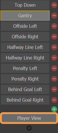
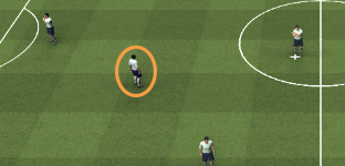
Click first on the player on whose viewpoint you wish to look from, this will select the camera position. Then click anywhere else in the virtual stadium to select the camera view angle. In the example below, the white cross shows the first click, we then click on the player circled.
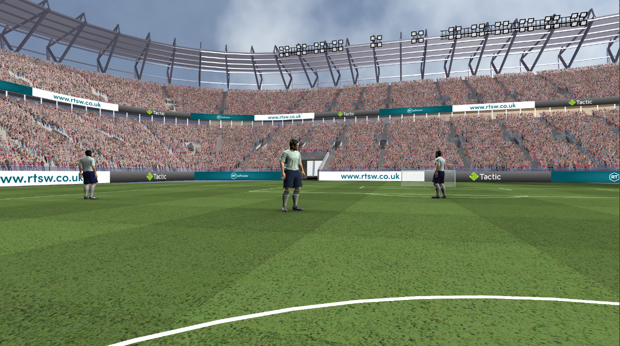
Below is the resulting camera angle.
Stadium View animation
It is possible to create camera keyframes within the virtual stadium to create animations between camera positions when playing back the analysis.
In addition to animating between preset cameras, you can also freely create a new camera keyframe at any point using the keyboard shortcuts and the mouse as follows:
- Translate on X axis: Hold Alt and drag the mouse horizontally using the mouse wheel
- Translate on Y axis: Hold Alt and drag the mouse vertically using the mouse wheel
- Translate on Z axis: Hold Alt and drag the mouse vertically using the right mouse button
- Pan: Hold Alt and drag the mouse horizontally
- Tilt: Hold Alt and drag the mouse vertically
Zoom: Hold Alt and scroll the mouse wheel
To start creating camera keyframes, first Select Virtual Stadium
Advance the video timecode (e.g. 5 seconds) and select/adjust the Stadium Camera as required.
Play the video and the Stadium View will animate smoothly from the first video timecode value to the second video timecode value.
Store the current Stadium View at the current timecode value using ..
Navigate the Stadium view(s) using the arrows.
The timing of the start and end of the animation can be adjusted.
e.g.
The Stadium View appears at timecode 0:00
The Stadium View remains stationary until timecode 2:00
The Stadium View animates to the new position though to timecode 4:00
The Stadium View remains stationary until timecode 5:00
This is achieved by setting the video timecode to 2:00 and Copy Previous Keyframe position
Copy Previous Keyframe position
Then setting the video timecode to 4:00
Copy Next Keyframe position
Align the Camera position and Stadium View
Use Pitch Calibrate and set up Tracking for the required Camera position.
Add Graphics as required …
The Stadium View will align with the Tracked Camera Keyframe.
Copy Tracked Camera Keyframe will synchronise the Stadium View to the Camera position as the timecode changes and can be used to define a smooth transition when the Stadium View closes.
Edit Keyframe Sequence
Display Motion Paths
Advance the video timecode and add a new keyframe position for the Graphic
Play the video and the Graphic will animate smoothly from the first video timecode value to the second video timecode value.
The animation can optionally be modified by inserting a new keyframe position at an intermediate timecode value.
The timing of the start and end of the animation can be adjusted.
e.g.
Graphic appears at timecode 0:00
Graphic remains stationary until timecode 2:00
Graphic animates though intermediate keyframe position at timecode 3:00
Graphic arrives at final keyframe position at timecode 4:00
Graphic remains stationary until timecode 5:00
This is achieved by setting the video timecode to 2:00 and copying the previous keyframe position
Then setting the video timecode to 4:00 and copying the next keyframe position
This is especially useful when using the virtual stadium and needing to temporarily pause a graphic while others continue to move.
An alternative method is to use the “Copy current keyframe” function whilst creating the motion path. In this case, to achieve the same result as above in this case place the graphic at 0:00 and before creating a motion path play the video until 2:00 and choose Copy current keyframe.
This creates a copy of the first keyframe at exactly the same location as the first keyframe, ensuring that the graphic stays in place. Now set the time code to 3:00, and move the graphic to an intermediate position to create a new keyframe, and again at 4:00.
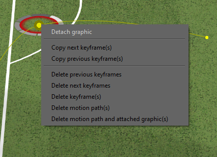
Delete Motion Paths
Right clicking on a motion path also gives you the option to delete the previous and next motion path to the currently selected position.
Clicking “Delete Motion Path(s)” will delete the entire motion path (every keyframe for that graphic).
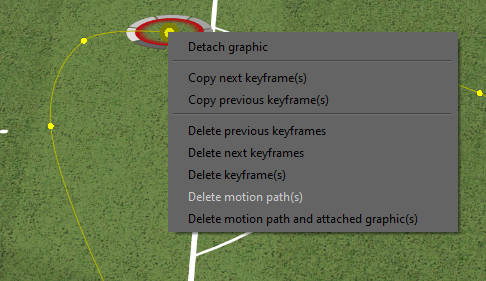
Below is the option to “Delete motion path and attached graphic(s)”, this will remove both the motion path and the graphic. To delete just the graphic and not the motion path, simply select (left click on) the graphic and hit the delete key.
Detach Graphic
It is possible to take a graphic of a motion path by right clicking on it and selecting “Detach graphic”. Then hold left click and drag it away from the motion path. The graphic will now not be associated with any motion path.
Playlists
Use a playlist to collate a particular set of Clips, Analysis or Bookmarks for presentation, rather than providing the entire contents of the Clips folder.
For analysis files, this is the only way to put them on the Presenter interface.
Add an element to a Playlist
To add an element (Analysis, Clip or Bookmark) to a Playlist, select the corresponding thumbnail with the Right Mouse Button and choose “Add to Playlist”. You can also select multiple analyses by holding the CTRL button and adding them all at the same time.at once and add them to the playlist.
View Playlist
To view the contents of a Playlist, select the Playlist tab
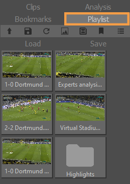
Save/Load Playlist
A playlist can be saved using the save button on top of the playlist view, a browser window will open allowing the location of the saved file (.playlist) to be specified. Any saved playlist can later be re-loaded using the load button.
Right Click on Playlist
A right click on an element (or multiple selected elements) will bring up an options menu.
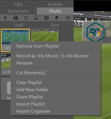
From this menu you can remove selected items from the Playlist, clear the whole Playlist or add new folders within the playlist. “Cut Elements” will remove elements from the current folder and allow them to be pasted (Right Click) into other folders.
Share (export) and import Playlists
Share Playlists will open a prompt to enter an export folder name.
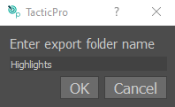
Entering a name and then clicking OK will create a folder with the “.plx” extension containing a copy of all the elements in the current playlist. This will normally be found in:
DesktopRTSWTacticPro*******PlaylistsExports
Where “*******” is the name of your current sport project.
This folder can be copied to another Tactic device and can then be imported using the “Import Playlist” function from the right click menu.
Present a Playlist
In Preferences, set the Clip View Type to Playlist to view the Playlist in Presenter mode…
The contents of the playlist will now be available from the Presenter interface.
Record Playlist
Playlists can be exported (Layed Off) in the same way as analysis sequences. See: “Record Analysis”.
Presenter Interface
The Presenter interface is designed for use on a Touch Screen for live presentations.
It enables you to load and play video clips and to add basic graphics.
Before using Presenter mode it is necessary to
- Choose a Camera
- Setup a Keyer (if required)
- Define the graphic colours and size etc using the Palette
- Create a Playlist if required
- Save/Load Playlist if required
NOTE: Complex animation sequences cannot be created or saved in the Presenter mode but it is possible to play back recordings of complex animation sequences that have been saved using Record Analysis.


NOTE: Navigation and Graphics tools are mirrored for left or right hand presentation and can be disabled if required.
- Clip Browser
- VT bar
- Play/Pause/Rewind/Slow Motion etc
- Graphics
Enable Presenter
Click on the Presenter Interface logo

Exit Presenter
To exit the Presenter interface hit F5 on the keyboard. When the Presenter Interface is closed you can also open it again with F5.
To refresh the presenter interface, hit F5 to close it, then F5 again to reopen it.
Toggle the interface from full screen to a window view by clicking on the Tactic logo.
e.g.
Change Presenter Tools
The graphic tools available in the Presenter interface are defined on the Presenter tab.
Drag and Drop Graphic tools to re-order the display order.
Drag and Drop any Composite Graphic tools to the Presenter interface or right click on the tool and choose “Copy to / move to” and select the Presenter interface.
Updated Graphics tools …
Re-open the Presenter interface to enable the updated tools …
Drag the tools left/right to scroll …
Change Presenter interface
In Preferences, set the interface tools on/off on the left or right hand side of the interface.
e.g.
Change Presenter logo
The default logo on the Presenter screen is the Tactic product logo …
To change the logo, in Preferences, replace the Brand Image file …
The new file MUST be the same name as the original and the same image type.
e.g.

NOTE: A .png format image with a transparent background will work best.
Change Presenter background and colours
To customise the appearance of the Presenter interface, in Preferences, replace the Background Image file or change the colours of the panels, Buttons and Sliders …
Tablet Control
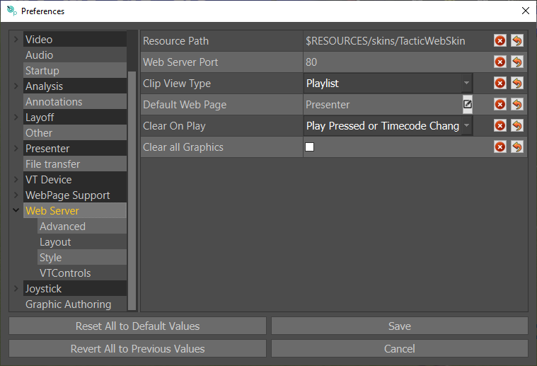
Set the web interface page, port from the Web Server tab in the Preferences menu and save the settings.
Selection of clips and buttons works the same way as the presenter interface – choose the clip view type to pick between clips/stories, and the Default Web Page chooses the composite styles page that should be displayed.
Operating the Web Interface
Access the Web Interface on Tablet or computer by navigating to the local IP Address plus the port of the machine Tactic is running on in Google Chrome. You can find the “Web Server Port” in Preferences under “Web Server”, the default is 80. Enter your IP then port in the Chrome address bar like in the example below.
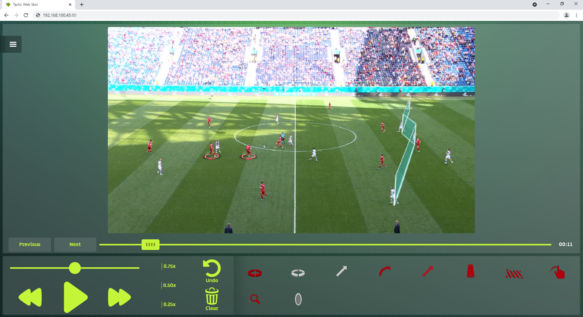

The transport options at the bottom left of the page allow you to play, pause fast forward and rewind as well as change the clip speed. The “Previous” and “Next button” will select the next or previous clip or analysis in the browser. The undo button will undo your last graphic and the clear button will remove all graphics placed in the web interface.
To place a graphic, short press a graphic at the bottom right, then short press again on the interface where you would like the graphic. Remember some graphics require multiple presses to define where they will start and finish.
To select a different clip or item from your story (this is defined in the web interface settings) hit the options menu at the top left (at the “1” marker).
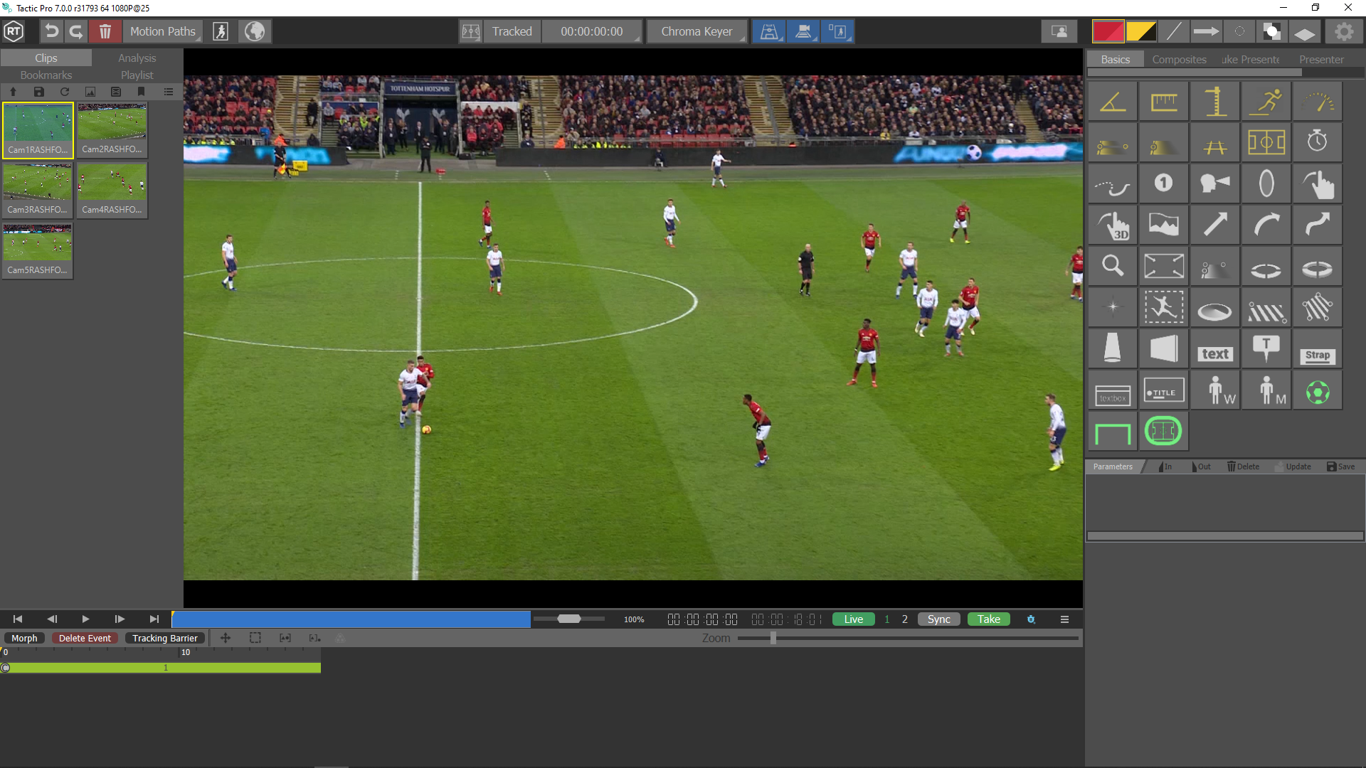
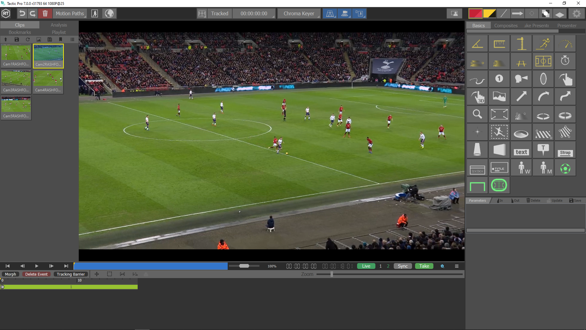
MultiCam
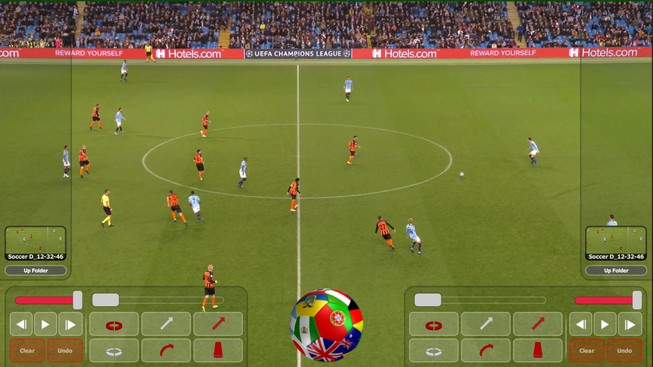
MultiCam is a Tactic Pro feature, it allows you to use 2-4 separate video inputs covering different camera angles.
Go to “Preferences” (top right-hand corner)
Go to the “Video” tab and enter the desired input channel (between 2 and 4) then save the settings.
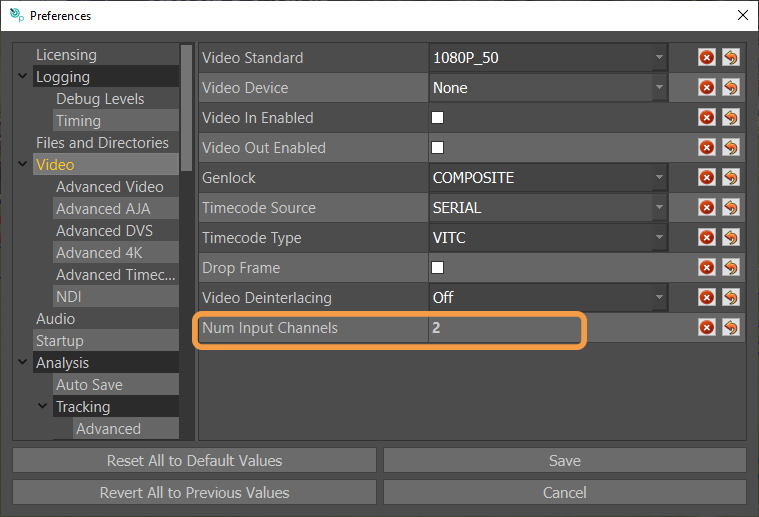
After clicking on “Save”, return to the main window and you will notice that the number of inputs is reflected there with the active camera being highlighted in green.
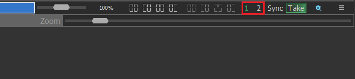
To alternate between cameras, you can click on the input number or use the corresponding keyboard keys (1, 2, 3 and 4).
Camera Morph
You first need to setup “MultiCam”
Select the 1st video clip with the first camera angle footage from the “Clips” library on the left-hand side, if the clip is newly added, hit the refresh button to reload the list.
Select the 2nd video input by pressing “2” on your keyboard or clicking on “2” in the timeline bar (As shown in the MultiCam guide”. Then load the clip with the 2nd camera angle footage.
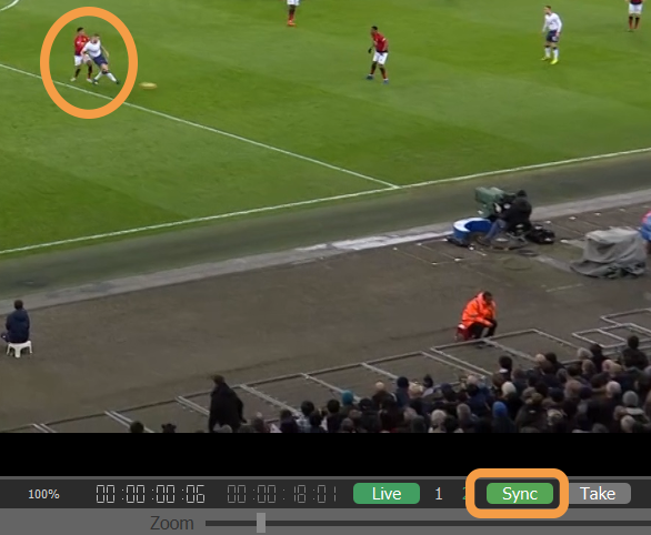
Note: If your 2 video clip frames are out of sync, they both have to be synchronised first.
- To synchronise both clips, in the first input, navigate to a recognisable frame and click on “Sync”
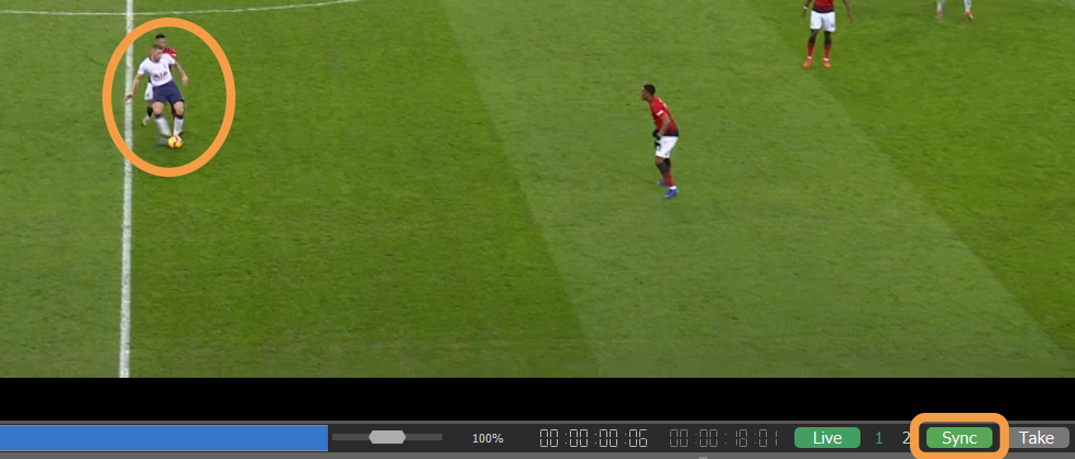
- Do the same with the 2nd input, navigate to the same frame, and click on “Sync”
Once your cameras are in sync, make sure that they both have key enabled. See here.
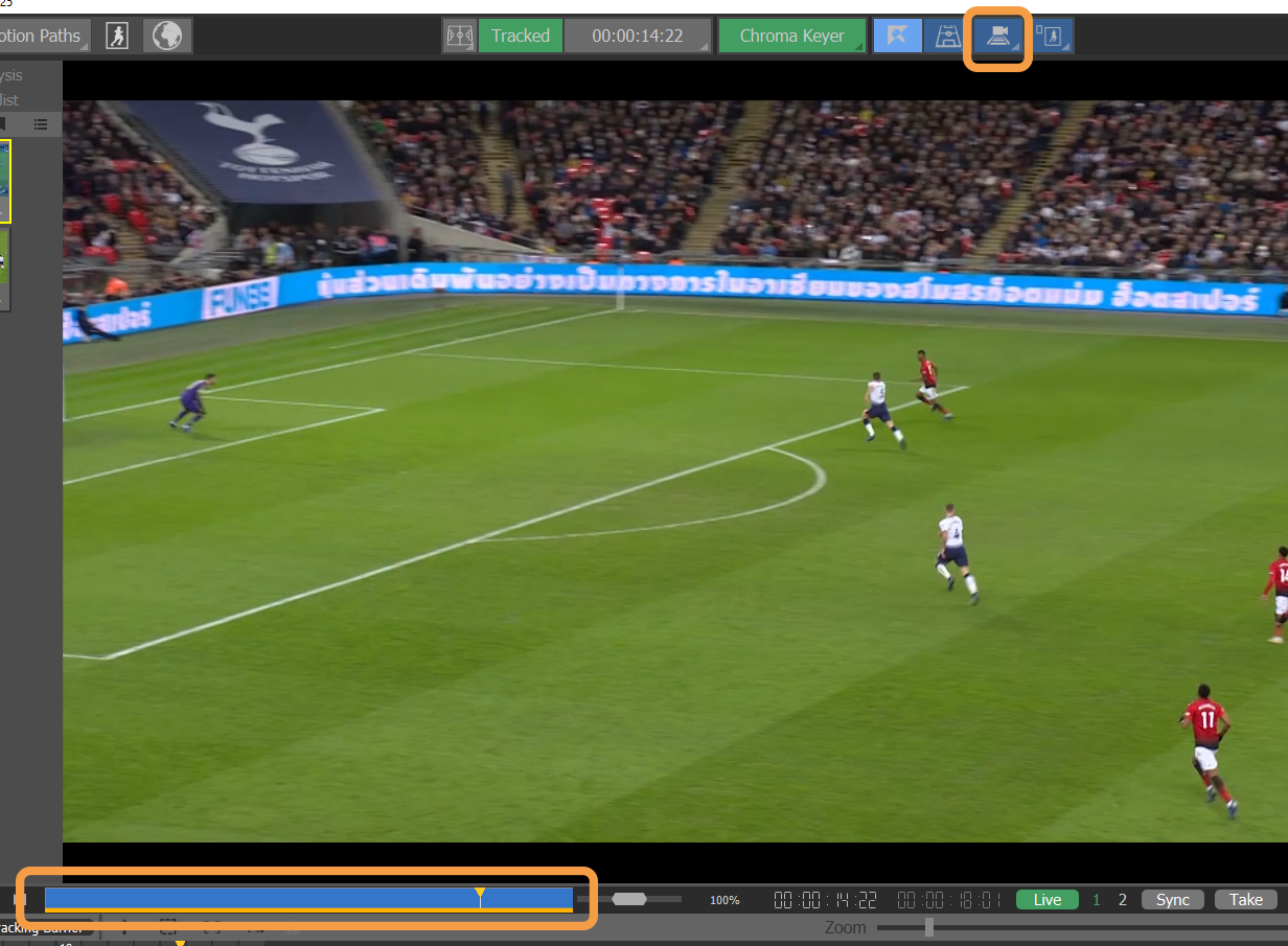
A calibration must be performed on both cameras to enable the Morph. For best results, calibrate both cameras at the frame which you wish to carry out the camera morph (Alternate between the 2 camera inputs to make sure the inputs are in sync).
Enable auto track for both cameras, by clicking on the Auto Track button. Once completed a coloured bar will appear under the whole of the scrub bar to show the auto track is completed.
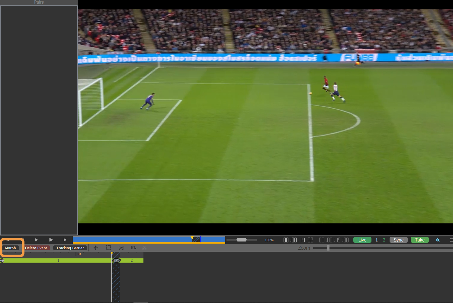
On the 2nd camera channel, click on “Morph”
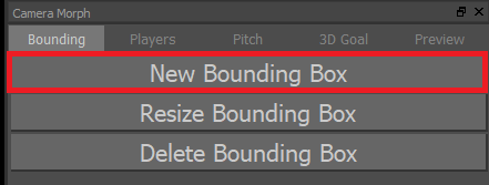
The camera morph settings will be displayed on the top right-hand corner, click on “New Bounding Box” and draw a box around a reference point in your video window using the left mouse button
Repeat the same process for any other players in the video.
If any boxes need to be adjusted, select “Resize Bounding Box”.
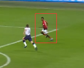
Once you have a bounding box around each player in your camera angle, go to the other camera angle and you should see the same coloured boxes. You will probably have to resize them to make sure they are correctly positioned on the correct player.
Add new Bounding boxes to any players that are not in the other camera view.
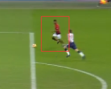
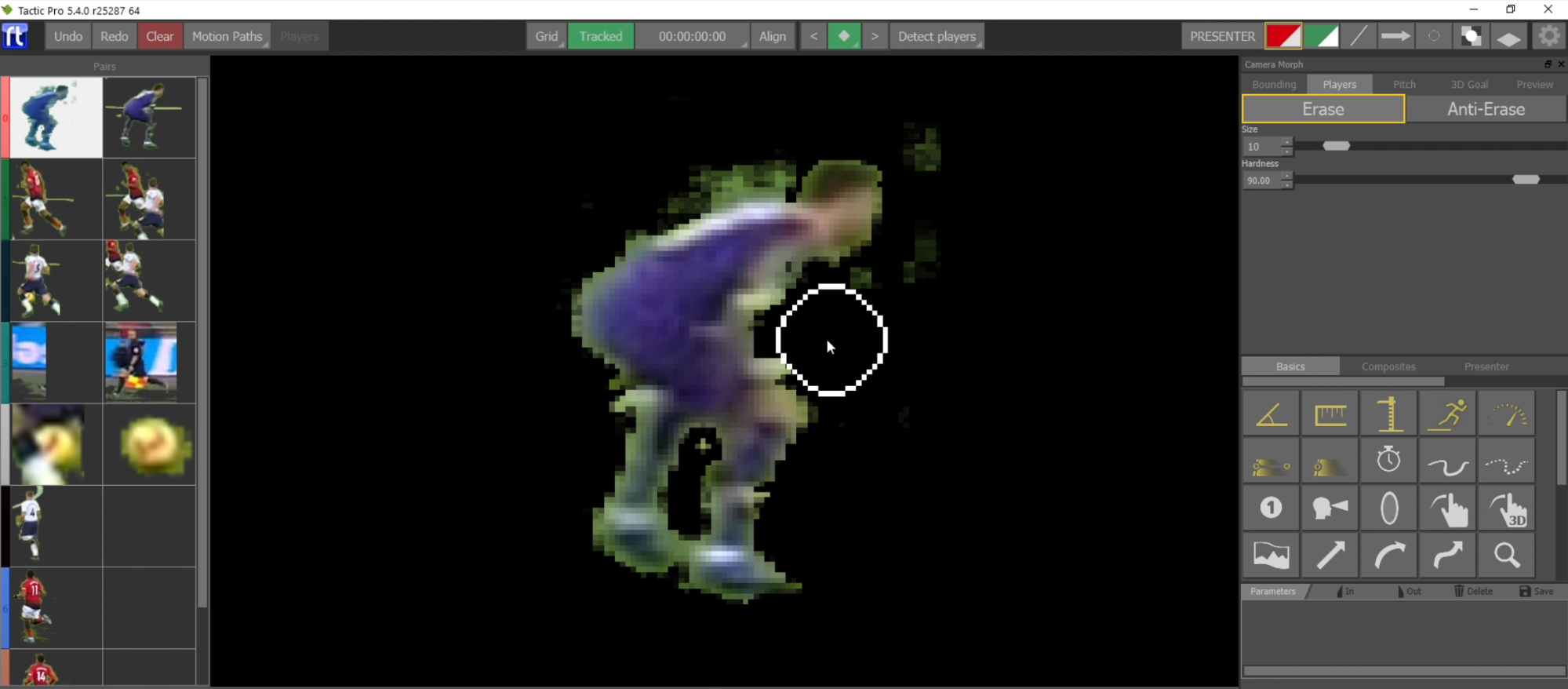
You will notice in the left-hand column that if a player is not on a keyed background (a white or advertising behind them) will have unwanted pixels. You will need to clean them manually by going to the “Players” tab in the morph setup.
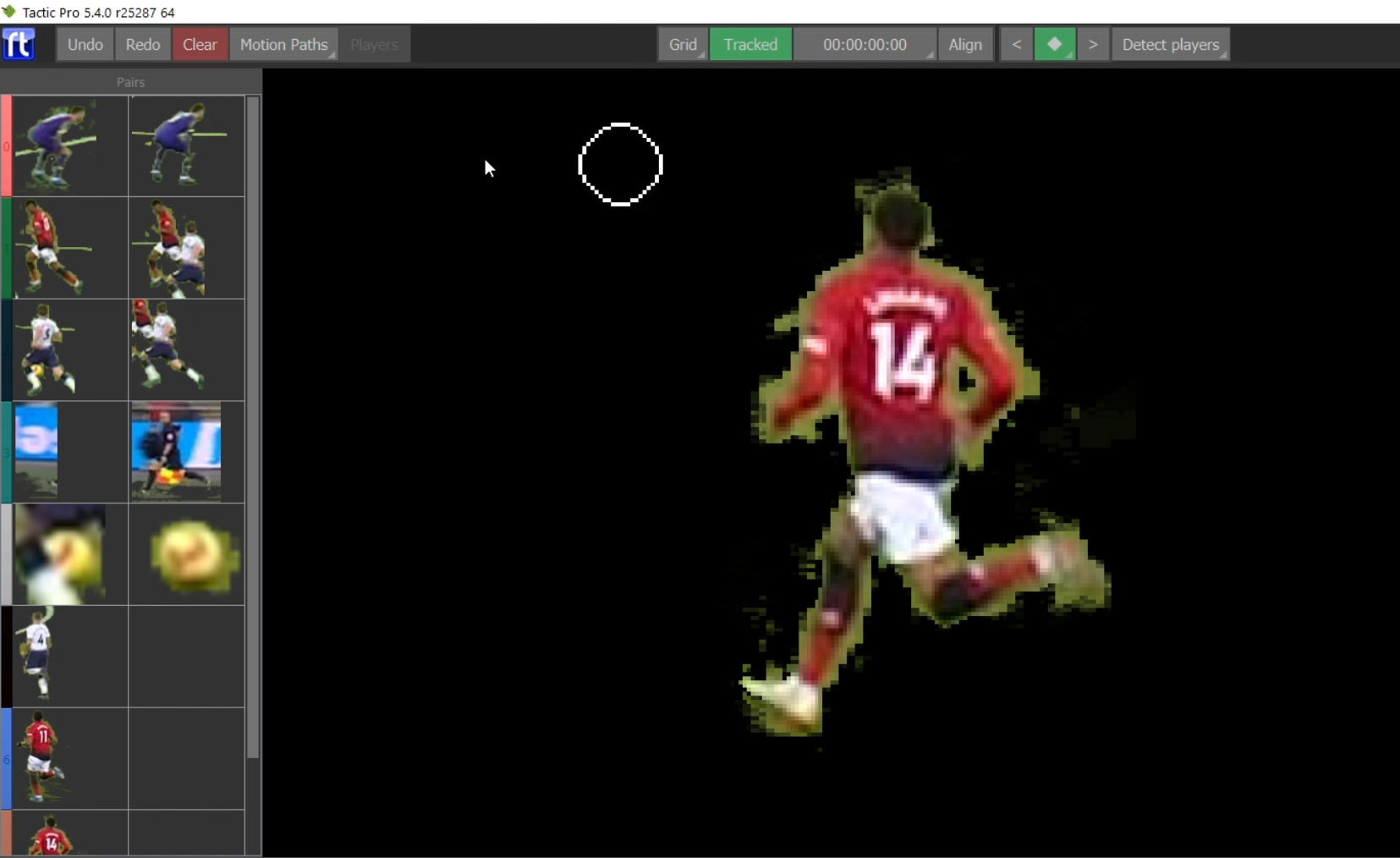
Click on the box in the left panel that corresponds to the player needing cleanup (A-S-W-D keys on the keyboard will move the cursor over the right box).
Now click on “Erase” in the player tab and move the cursor to the large video window to erase the unwanted.
You can adjust the size of the cursor with the mouse wheel or the “Size” slider. The Hardness slider will adjust the softness of the edge.
If you make a mistake and erase some of the player, click on “Anti-Erase” to paint these pixels back.
Repeat the same process for objects that appear on both camera frames
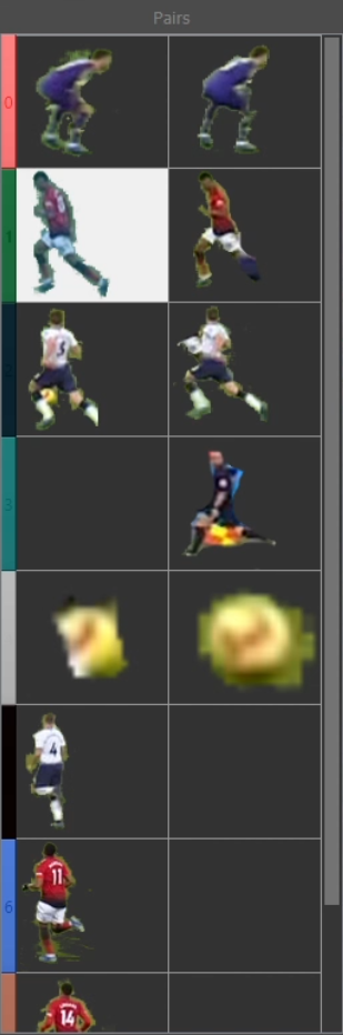
From the Camera Morph settings panel, go to “Pitch” click on “Auto Fill”, you will notice that the players/ref would disappear.
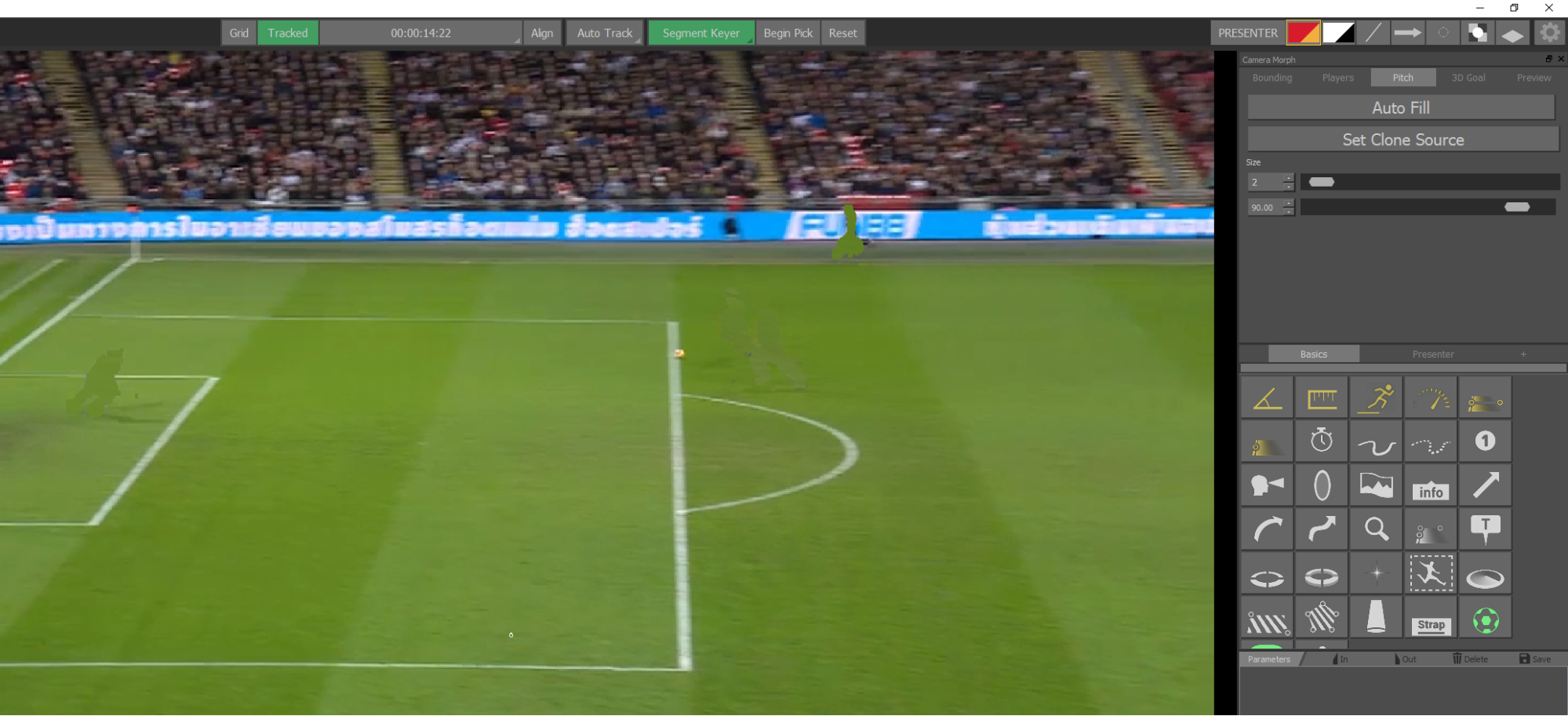
Where the players have left empty spaces in the lines or advertising hoardings, you now need to fill those gaps using the clone tool by cloning the surrounding shapes/pixels.
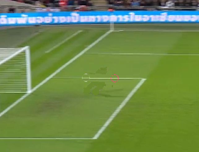
Click the “Set Clone Source” button in the pitch tab, or hold down “CTRL” and left click an area clone. Move the area you need to fill and left click (note you can hold the left mouse button and drag to paint the cloned area).
To allow a smooth angle transition without introducing noticeable distortion, you will need to place a virtual goal to replace the existing one that gets distorted between the two different camera angles.
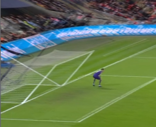
From the Camera Morph settings panel on the left hand-side, click on “3D Goal” and tick both “Enable Goal” and “Tint for Editing”. This should draw a virtual 3D goal, you can change the parameters from the same panel on the side.
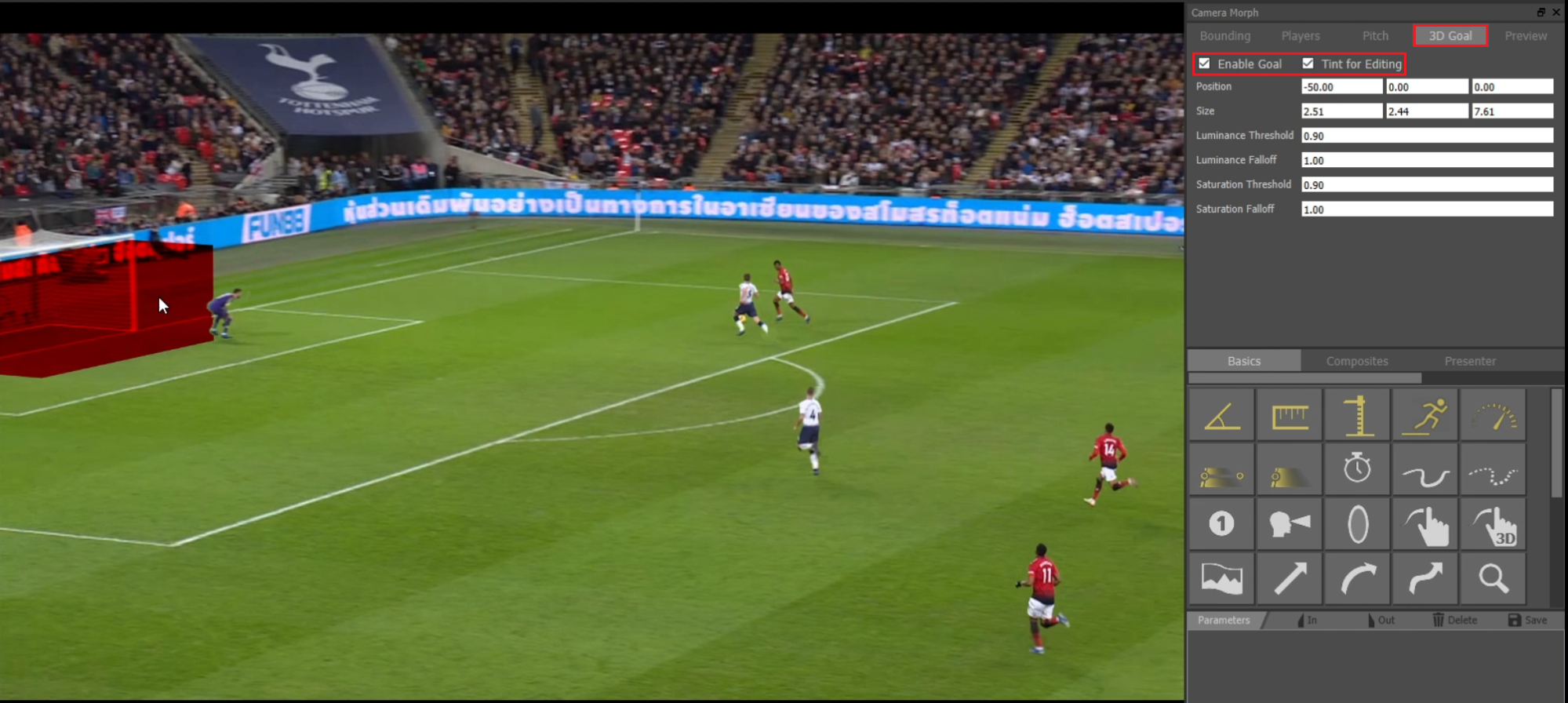
Once you’re happy with the 3D Goal positioning and dimensions on the pitch, click on the “Pitch” button (Camera Morph panel on the side) as the actual goal needs to be erased (use the clone tool to clear it).
This process needs to be performed on both camera angles.

You can now remove the 3D Goal tinting to have a preview of the added virtual goal on the pitch
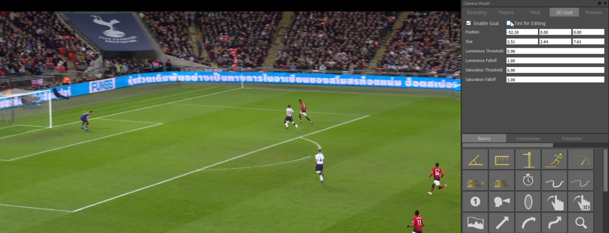
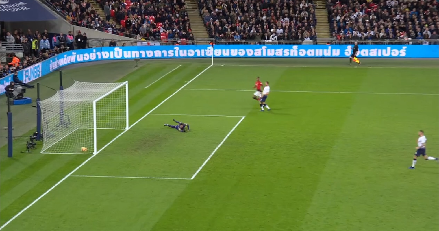
Record to Disk
Record to disk allows background recording of clips from the incoming SDI feed whilst the operator can either work on other clips, or rewind the record chain to create and lay off analysis sequences. This is a suitable workflow for when working on Live sporting action, allowing Tactic operators to work standalone without the need for a record channel of a replay server. Pausing or rewinding does not stop the record,operators can return to the live feed at any point.
Go to the Preferences menu > Layoff > VideoRecord and set a directory to save clips.
It is recommended that the record to disk directory is on a separate disk than the system disk.
You can also set a name prefix for recorded video and set a record video format (AVC100 recommended)
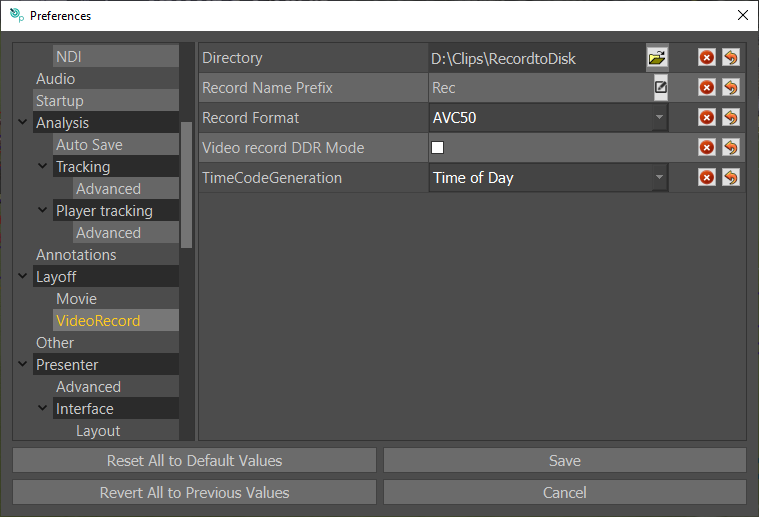
You need to set your video-in device in “Preferences > Video > Video Device” and ensure that “Video in Enabled” is ticked.
Click on “Save” to save your settings.
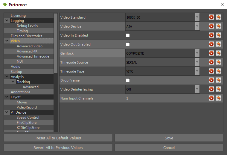
From the Settings cog wheel, choose “Video Record”
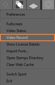
The “Video Record” panel should appear as below.
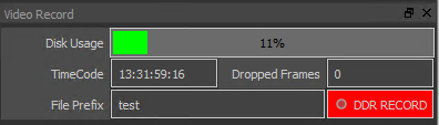
Clicking on the “Live” button in the VT toolbar will eject the current clip and you will be able to see the live input and you can now click on “DDR Record” to start recording.
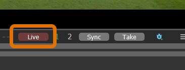
Once the recording has started, the DDR button will turn red to indicate that Tactic is recording. A new clip is created in the folder specified in the “VIdeo Record” directory in preferences and the live button will now be green.
However, it is not required to stop the record and load the clip to start adding analysis. Click on the live button to go back to the live input and the button will turn red. At any point, you can now pause the video, or use the jog control (below) to go back in the video.
Create a Mark in at the point at which you wish your analysis sequenced to start (Letter “I” on keyboard) and a Mark out where you wish the analysis to end (Letter “O” on keyboard). You will now see the scrub bar turn blue to indicate that some video is loaded and ready to have some analysis graphics added.
Once you have finished the analysis, you can save it as an analysis for later recall, or layoff as a finished clip. At any point, you can click on the Live button again to return to a live input. So if some important action takes place whilst you are creating an analysis sequence, it is not lost.
EVS File Transfer
This allows the Tactic operator to transfer clips to and from an EVS replay server over ethernet. Once a clip has been made on the EVS, the Tactic operator can request that clip, and it will be transferred to the Tactic internal hard drive independent of the EVS operator. Tactic can then add graphic analysis sequences, and then send the completed analysis sequence back to the EVS for playout. This workflow negates the need for an output channel of EVS dedicated to the analysis system.
Setup is done in “Preferences” under “File Transfer” please refer to EVS File Transfer Setup in Appendix A for full details . In here you can set up the codec file, ip address of the device transferring from and to, and the local clip destination.
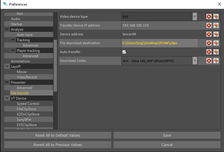
To start the transfer, go to preferences and “File Transfer”
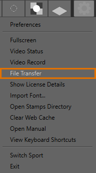
The file transfer window will appear in the bottom right, click on the “Download” button.
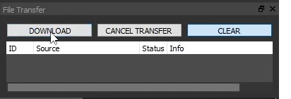
In the resulting window, enter the clip id of the clip you wish to transfer
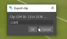
And click OK.
You will see the progress of the transfer in the file transfer window, when completed, it will be shown as 100% and the clip will be available in the folder specified in preferences under “File Download Destination”.
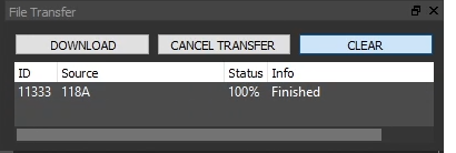
If this folder is the same as the current “File Clips Store” folder, the clip will also appear immediately in the clip browser to be used in Tactic.
A clip can also be transferred back to EVS by right clicking on the clip and choosing “Send to Device”.
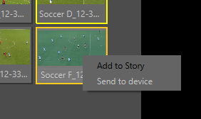
In the resulting window type the location on the EVS you wish to send the clip to and click OK, again the file transfer window will show the status of the transfer.
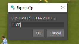
If “Auto Transfer” in the preferences window is checked, when laying off an analysis sequence, the finished layoff will automatically be transferred to the EVS. In this case, choose the EVS location as the “Record Filename”.
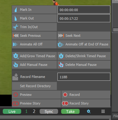
Appendix A – Preferences Reference
NOTE: The exact Preferences available may depend on software License options.
NOTE: Restart Tactic for any changes to take effect.
Licencing
License Server, Default is localhost. “localhost” should be used when using a license dongle or software license. If using a license server, the IP of the server goes here.
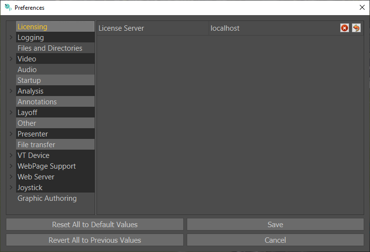
Logging
Enable File Logging: Default on.
Log File Directory: Default blank.
Log File Name: Default blank
Debug parameters should ONLY be used on instruction from RT Software.
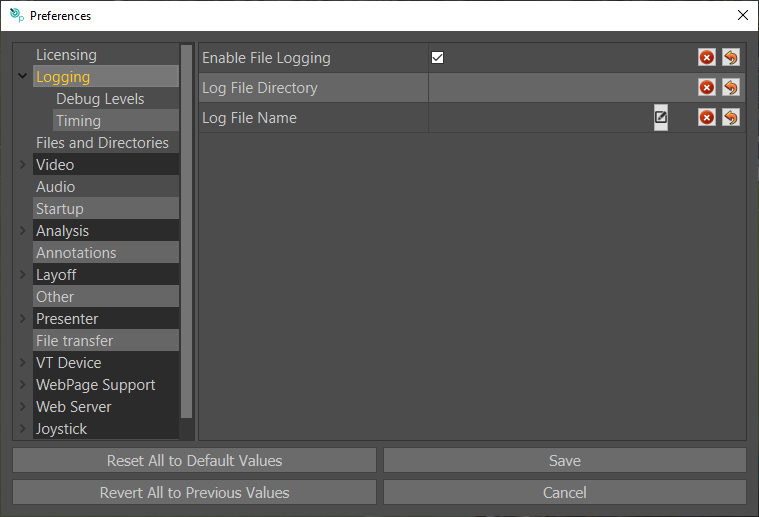
Debug Levels
Debug parameters should ONLY be used on instruction from RT Software.
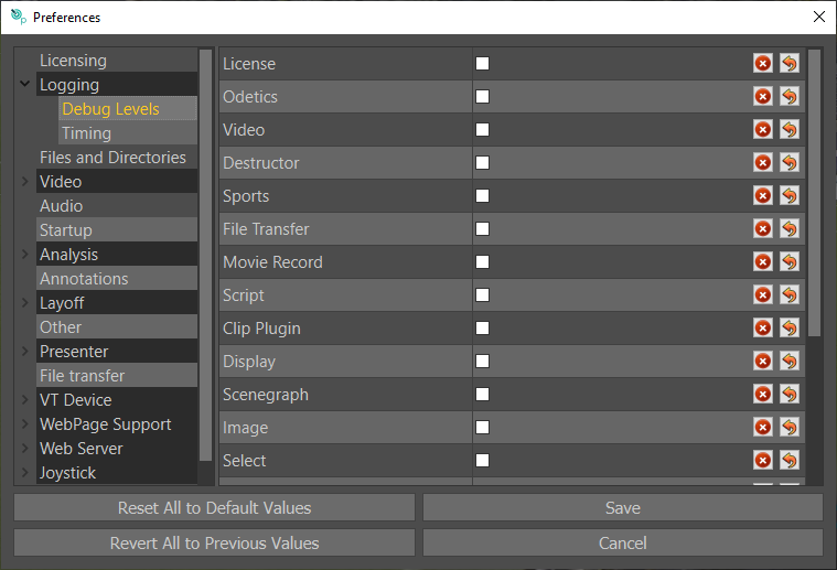
Timing
Timing Level: Default setting is off. Timing level will display information about how long it is taking for graphics to be rendered across various processes.
Show Scope: Default setting is off. Gives a live scope of GPU Processing usage.
Show GPU: Default setting is off. Shows live memory usage details.
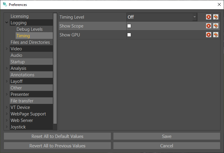
Files and Directories
Project parameters should ONLY be used on instruction from RT Software.
RTSW Directory: This is the directory where most user generated content is saved.
The following project folders are where default content is stored and should not be changed.
Main Project: Default is $RESOURCES/TacticDraw/TacticDraw.prj
Extra Project 1: Default is $RESOURCES/TacticDraw/Tacticadv.prj
Extra Project 2: Default is $RESOURCES/TacticDraw/Tacticlite.prj
Extra Project 3: Default its Blank.
Extra Project 4: Default its Blank.
Global Font Directory: Default is $RTSW/Fonts. This is where imported fonts are stored.
Sports Settings Directory: Default is $RTSW/Fonts. The folder where sports user generated content is saved.
Sports Package Directory: Default is $RESOURCES/SportsPackages
Sports Package to Load: Default is Blank
Sports League to Load: Default is Blank
Stamps Directory: Default is $RTSW/Stamps. This defines where imported stamps are saved.
Screenshot Directory: Default: /RTSW/screenshots. This is the location where screenshots (when taken from the button next to the clip menu) are saved.
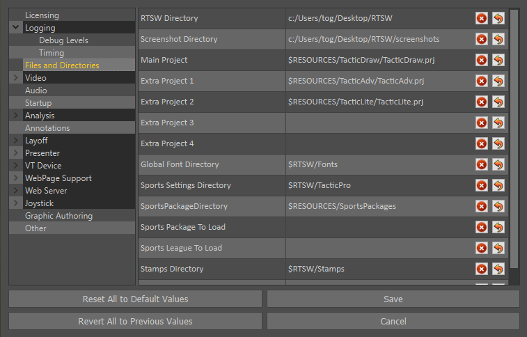
Video
Video Standard: Set this to match the format of the video clips you intend to analyse.
Video Device: Set this to match the video card type. e.g. AJA
Video in Enabled: Default is off.
Video out Enabled: Default is off.
Num input Channels: Default is 1.
Genlock: Default is COMPOSITE.
Timecode Source: Default is SERIAL.
Timecode Type: Default is VTC.
Drop Frame: Default is off.
Video Deinterlacing: Default is off.
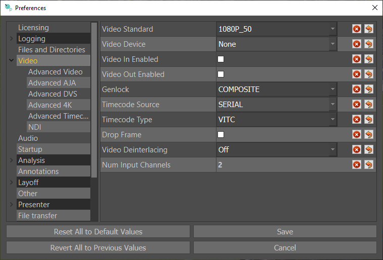
Advanced Video
Flicker Filter: Prevents thin line from flickering on interlaced video Default is check.
Sync to Monitor: Synchronises the video output to the display to remove screen tearing on the monitor out. Default is unticked.
Video Format Mismatch Prompt: Turns on warning message if selected clip is different format from Tactic settings. Default is on.
Horizontal Sync: Offsets the Genlock in pixels. Default is 0.
Vertical Sync: Offsets the Genlock in Lines. Default is 0.
Enable Anc Data: Enable Ancillary data on output. Default is disabled.
Watchdog: If enabled Tactic will send watchdog data to allow use for fail safe features on AJA Corvid 24s and DVS cards that support this feature. Default is unticked.
Video Card Delay: Offset Video Card Delay. Default is 2
Multisampling Sample Count: Increases effectiveness of anti aliasing, higher is more effective but slower. Users should leave as default unless instructed otherwise.
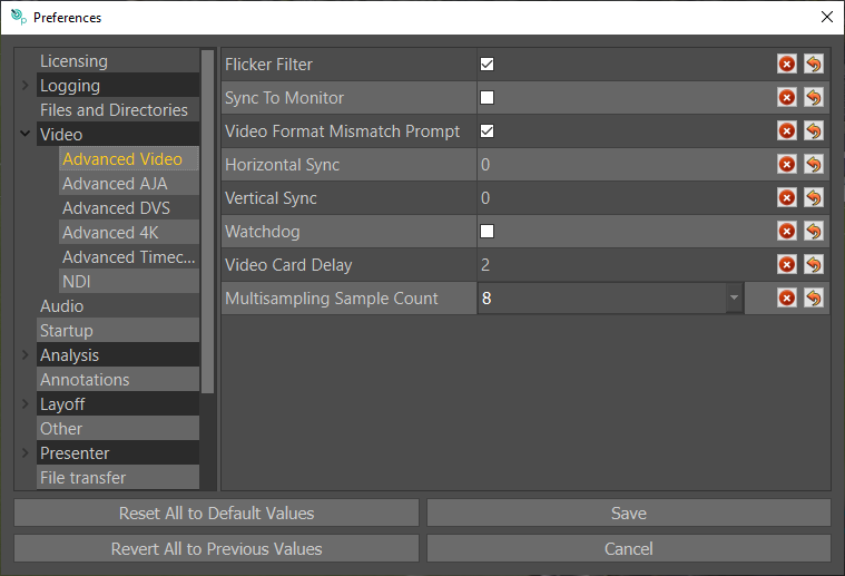
Advanced 4K
4K TSI Enable: Default is off. Uses TSI four tessellation outputs instead of quadrants over four 1080p outputs.
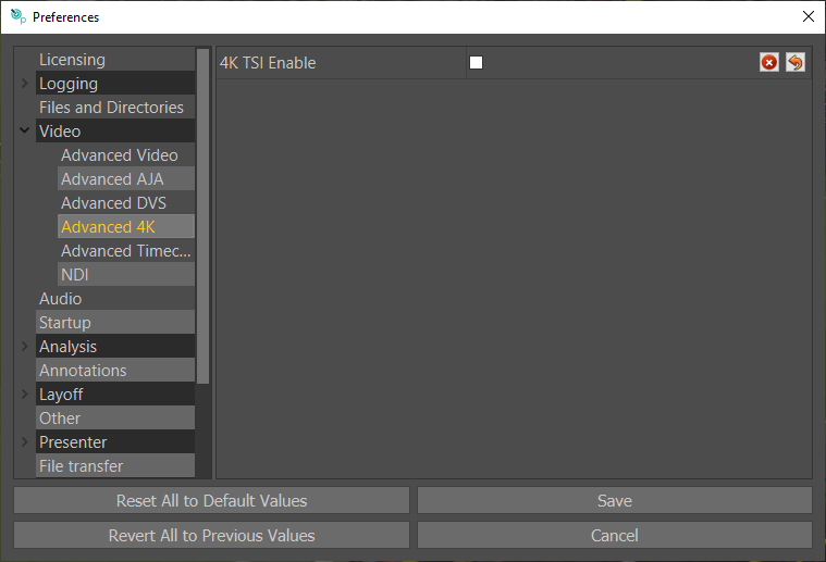
Advanced Timecode
Ignore VITC2: Default is off.
NTSC+PAL field flag: Default is off.
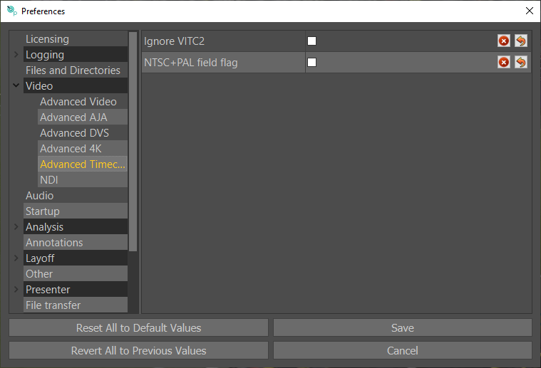
NDI
Enable NDI Output: Default is off.
When enabled Tactic will output an NDI feed of the video out using the defined “NDI ID”
NDI ID: Default is the PC’s Name. The NDI ID is what Tactic will broadcast on if “Enable NDI” Output is Enabled.
NDI Source 1-8: Default is not set.
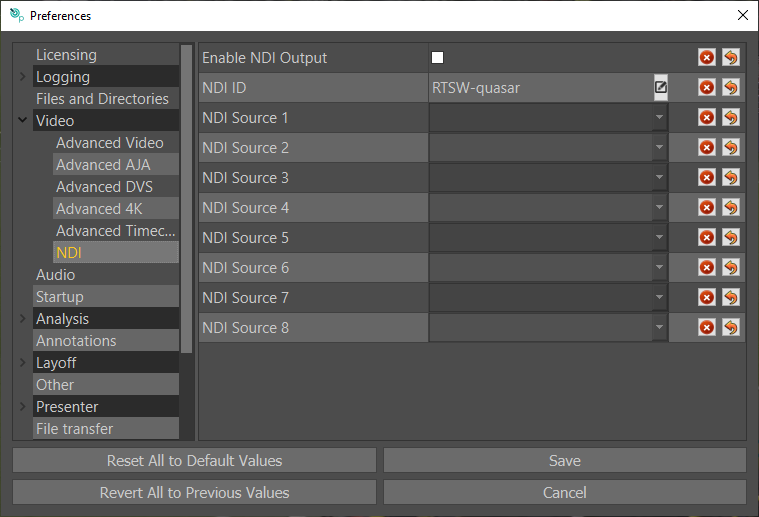
Audio
Audio On/Off: Default is unchecked. When enabled Tactic will play the audio of the clip or live input on the video out.
PC Sound card Output: Default is unchecked. When checked this will output the audio of the clip or live input out of the PCs default output.
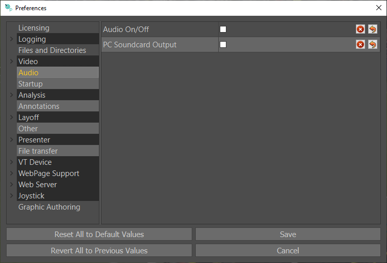
Startup
Threaded Project Load: Default is unchecked. This allows projects to load much faster if using a dedicated GPU. It is recommended to only use this when using a machine which only has an Nvidia GPU.
Start Fullscreen: Default is unchecked. When checked, Tactic will start fullscreen.
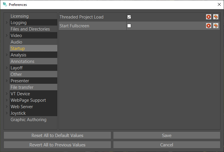
Analysis
Default Pause Duration: Default 4 seconds. Defines how long manual pauses last after hitting play/space.
Skip Length: Adjust the length of skip when pressing “CTRL+J” and “CTRL+L” keyboards shortcuts. Default 3 seconds.
VT Pre Roll: Default 3 seconds.
VT Post Roll: Default 3 seconds.
Check For Unsaved analysis: Will prompt if the user attempts to load a clip before saving their analysis.
Always Animate Off and Pause: Off.
Default Camera Morph Duration: Default 1 second.
Default Image Blend Duration: Default 1 second.
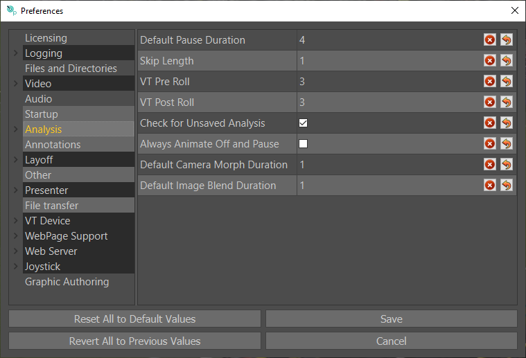
Auto Save
With “Auto Save Analysis” turned on, Tactic will automatically save its current state and analysis graphics. On Relaunch, Tactic will revert to its previous state.
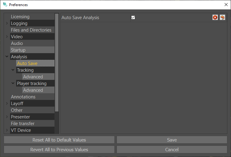
Tracking
Tracking Profile: A higher tracking setting (low, medium, high, ultra) will improve the accuracy of the tracking. However, faster GPUs are recommended for higher profiles.
You can trade off real time tracking for better tracking.
The “Custom” profile is fine tuned to the parameters used by the profiles.
Always render selected pitch model: Default off.
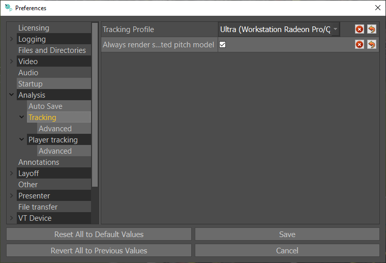
Advanced Tracking
Advanced Tracking parameters should ONLY be used on instruction from RT Software.
Tracking Pool Size: Default is 1. Limits memory usage by setting the maximum number of channels that can be simultaneously tracked in the background (use 0 for unlimited).
Advanced Feature Debugging: Default is unticked. Enable collection of features for advanced feature tracker.
Enable Live Tracking: Default is unticked. Tick to enable live tracking, for use with live video in.
Limit Auto Track Region: Default is unticked. Enable to limit auto track to mark in/out. When abled, expanding the mark in /out region will require re-tracking.
Reuse computed world features: Default is unticked.
Raycast world features: Default is unticked.
Line tracking refine window: Default is 0.
Enable Tracking Post-Processing: Default is “Line Tracking Only”.
Post-processing window size: Defaultis 32.
Post-processing jitter frequency: Default is 8.
Post-processing chunk frequency: Default is 10.
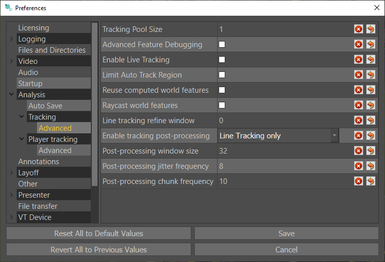
Player Tracking
Selecting “Model Type” will allow you to choose a Player Detect model specific to your sport which may give better results. The default model installed with Tactic Pro is the “Football” model which works best with Football players, and sports where players wear similar types of clothing such as Rugby. But may not work so well with sports where players wear a lot of protective gear and helmets.
In this case you may find the “Generic model” will work better. First download the “Generic Player Detect Model” from https://rtsw.co.uk/software-downloads/#tab-2. Unzip the package and run the .exe to install.
Now restart Tactic and choose “Generic” from the model type in the relevant preferences section below. A restart of Tactic is required.
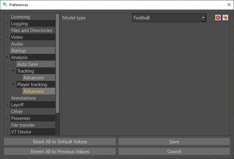
Annotations
These parameters allow you to customise the colours of the visual aids when working with motion paths. Note: Splines are displayed when motionpaths are enabled.
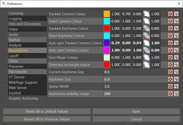
Layoff
Loop Preview: Default unticked. When previewing a story it will cause it to loop back to the beginning of the story once it reaches the end to make a continuous loop. Ideal for demos.
Movie
Directory: Set this to the file path of the base directory to store exported video clips (layoff). e.g. DesktopRTSWlayoff
File Format: Select preferred video file format for exported clips (layoff).
Video Codec: Select preferred video codec for exported clips (layoff).
Movie Quality: Select the required movie quality.
Audio Codec: If audio is present on original clip, set the audio codec.
Audio Channels: Select the number of audio channels to record.
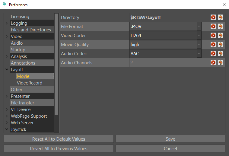
VideoRecord
Directory: Default is blank. This defines where the video record will save. …/desktop/RTSW/Layoff is a recommended directory.
Record Name Prefix: Default: Rec. This is a prefix that will go at the start of each layoff file name.
Record Format: Default AVC100 (recommended). Select the video format of your layoff.
Video Record DDR Mode: Enables “Record to Disk” allowing operators to pause, rewind and create analysis sequences on video while recording.
TimeCodeGeneration: Chooses whether timecode associated with a recorded clip will start at 0 or be the time of day.
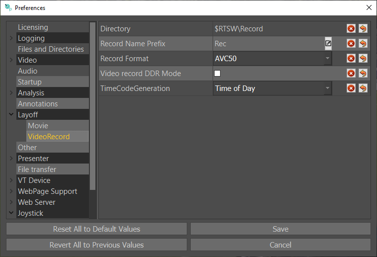
Presenter
Presenter FIle: Default location of Presenter interface
Presenter Page: Default Blank
Presenter Display: Default Windowed
Clear On Play: All graphics automatically clear when video clip plays
Clear All graphics: Default Off
Clip View Type: Clips/Bookmarks/Playlist
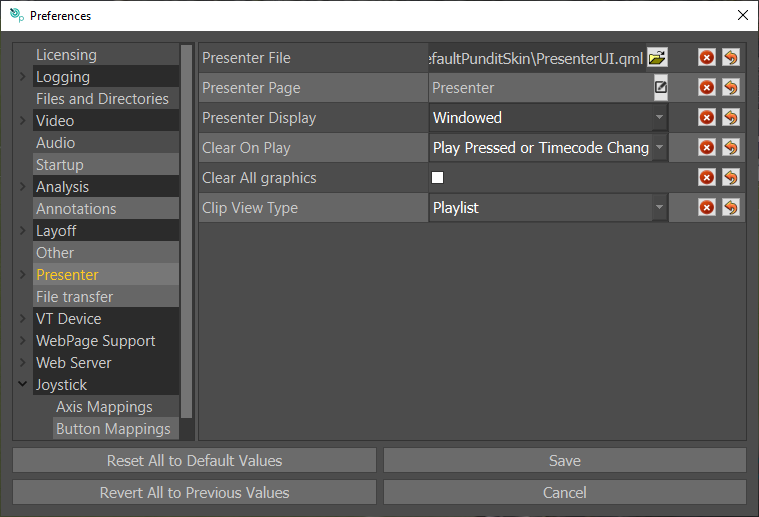
Presenter Advanced
Use Player Detections: Default on. This makes graphics placed on the presenter interface snap to the existing player detections.
Disable Touch Mouse Emulation: Default Off
Touch Click Tolerance: Default 5
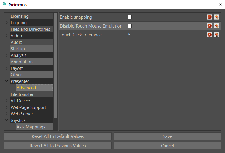
EVS File Transfer Setup
System layout
The system will consist of these main elements:
- An EVS XT video server
- A Windows PC running a compatible version of Tactic (minimum 6.1.0)
- A server machine running XSquare and XTAccess
- A network-shared hard disc space. From now on we’ll call it “Tactic shared folder” and it can be some sort of a separate network drive or in fact just a Windows shared-folder on the Tactic PC.
- An ethernet network connecting all these elements together
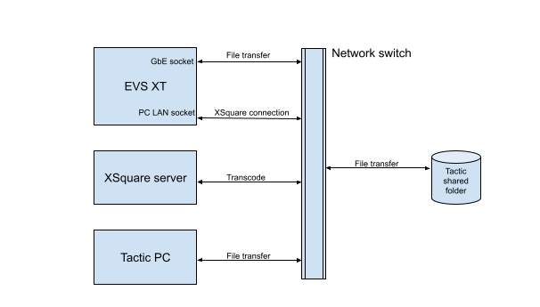
Basic XSquare Configuration
Before files can be transferred between the EVS and Tactic machine, some configuration needs to be done on the EVS side. We provide some basic instructions below. However, for full details, please consult the full EVS documentation here.
Association tool
The XSquare/XTAccess applications will each be accessed by an IP address and will have to be “associated”. This is done by an EVS application called Association Tool. This is installed together with XSquare on the XSquare server.
- Open the Association Tool interface on the XSquare server
- From the right table on the interface drag the XTAccess line to the left column where the XSquare IP address or hostname is displayed, in this case it is named lancer09.
Before the association XTAccess will be “not linked” as on the image below:
Linking:
Network space configuration
Before configuring Tactic a shared network disk space needs to be made available to both Tactic and the XSquare server. In this example it is manifested by a simple Windows shared folder on the Tactic PC and is named as \POUNCYEVSShare.
Name of the PC: POUNCY
Name of the folder: EVSShare
This folder will be mounted as a mapped network drive on both the Tactic PC and the XSquare server.
This network address will have to be added to these properties in Tactic preferences:
File Transfer / File Download Destination: to tell XSquare that clips from the EVS will be transferred here.
FileClipStore / Clip Directory:
- This is how the downloaded clips will become available in the Tactic clip list for telestration.
- Additionally, any video files put in here can be uploaded to the EVS.
Layoff / Movie / Directory: This can be a subfolder in the shared folder and it is set so that a recorded telestration can be automatically uploaded to the EVS after the telestration has finished and an output file is produced. In this example this will be \POUNCYEVSSharelayoff.
See where to make these settings in the Tactic configuration section below.
Tactic configuration
File Transfer Preferences:
Find File Transfer Preferences in the main Preferences window:
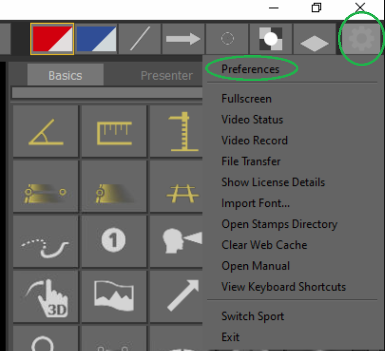
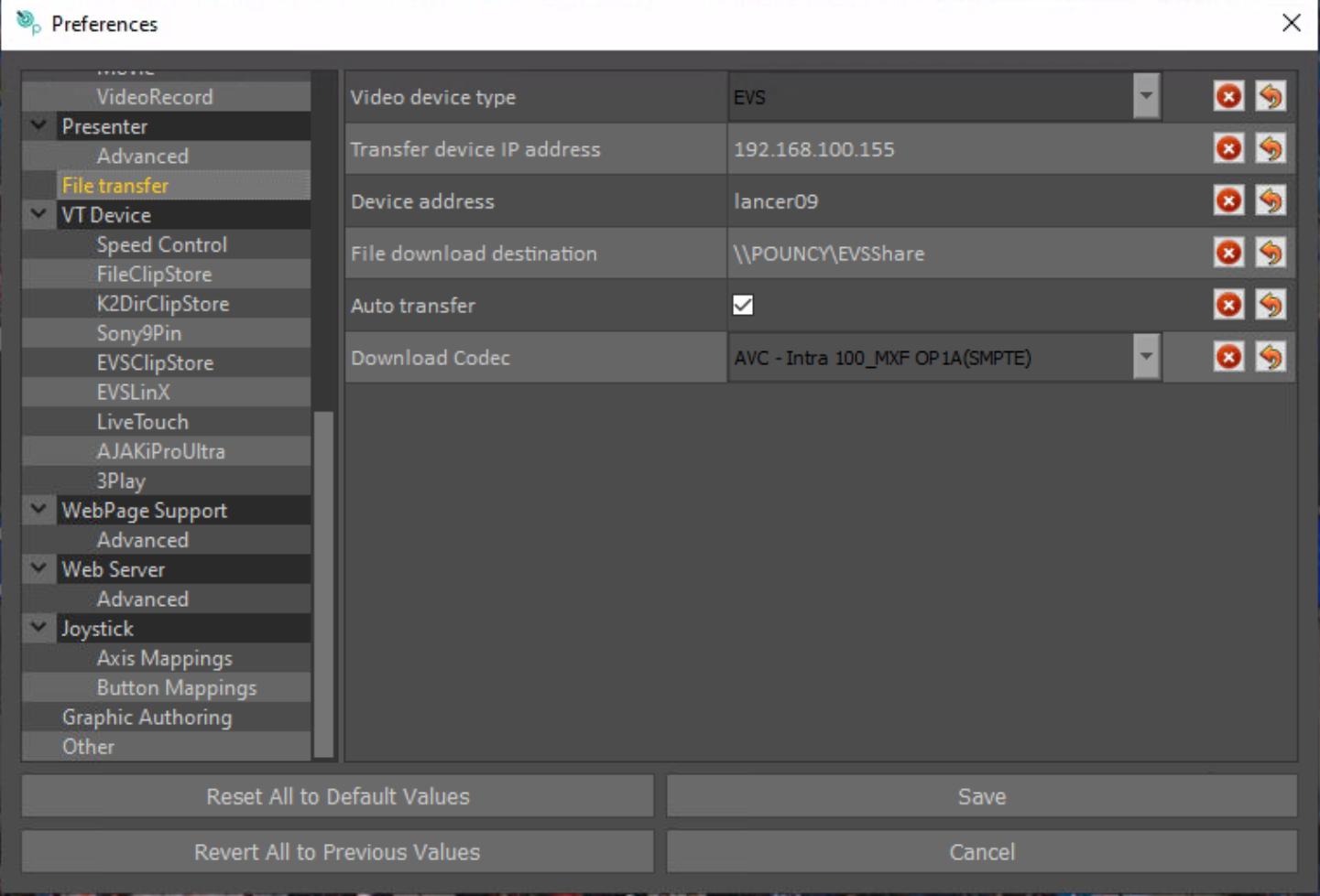
Video Device Type: the video server device, in this case EVS
Transfer device IP address: on the EVS it is one of the GBE network port’s IP address that’s connected to the network
Device address: The IP address or host name of the XSquare server
File download destination: The Tactic shared folder path. This has to be accessible by both Tactic and XSquare
Auto transfer: enable this to automatically upload a laid-off telestration from Tactic to EVS. The upload will start once the layoff has finished and the output movie file has appeared in the shared folder. For this it is best to set the layoff output to the shared folder set in File download destination or its subfolder. The file will be transcoded by XSquare to the codec currently configured in the EVS.
Download codec: choose from a selection of video codecs to be used for downloading and transcoding clips from the EVS to the shared folder.
FileClipStore preferences
To be able to see the downloaded clips in the Tactic clip list, set the Clip Directory to that of the Tactic shared folder used for downloading clips from the EVS. Also specify this at File download destination in the File Transfer preferences.
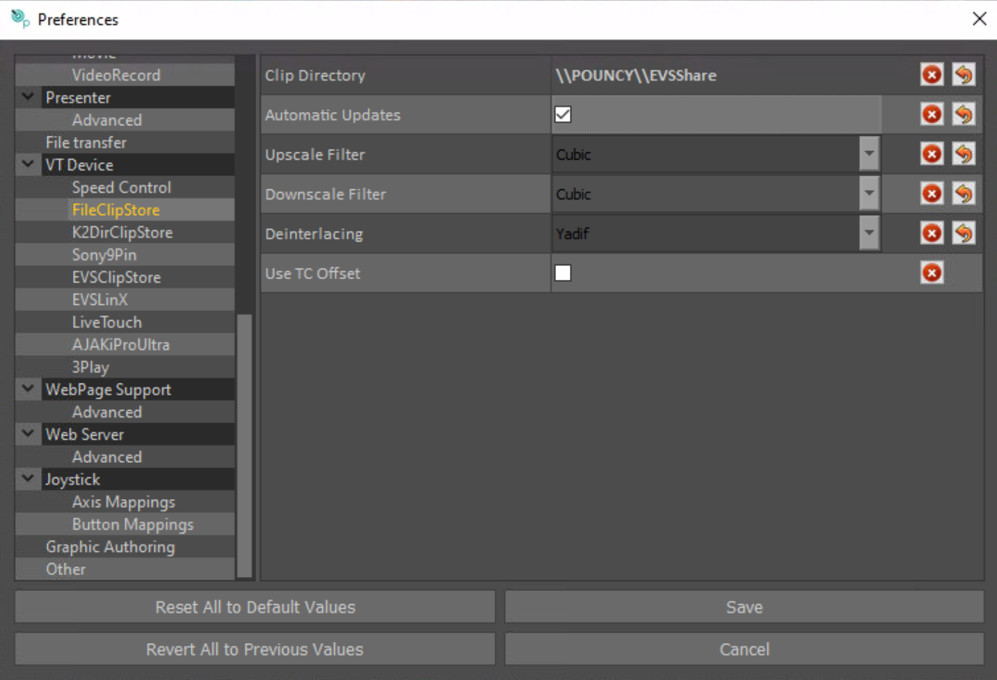
Layoff preferences
Directory: set this to a folder inside the shared disc space in order to “autotransfer” the laid-off clip to the EVS.
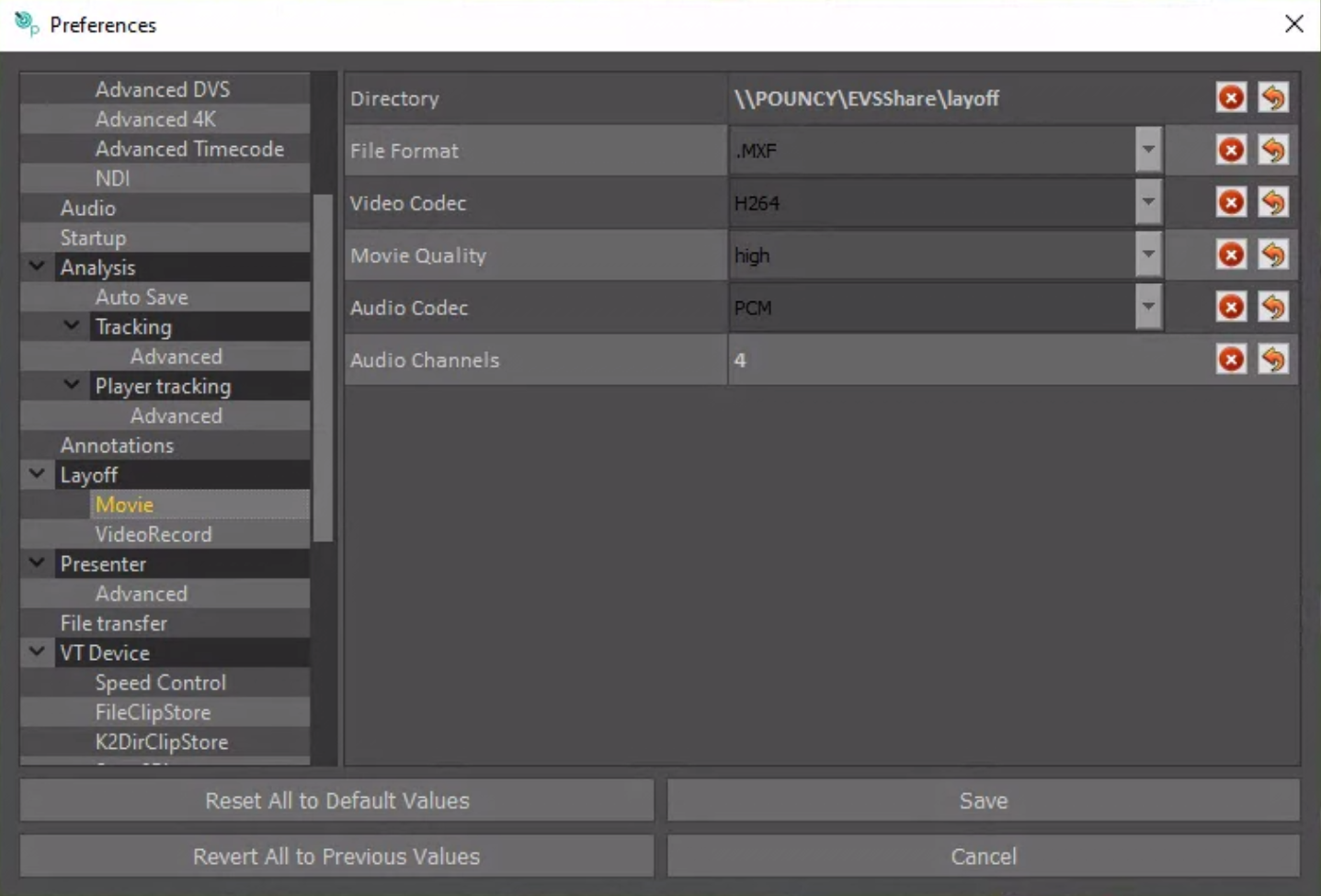
File Transfer interface
The user interface can be accessed via the main drop down menu in Tactic.
This will open the interface that allows to download clips, cancel transfer, view and clear notifications from transfer processes:
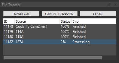
Download: Sends a transfer request to the EVS via XSquare after setting the clip LSM ID in the pop-up interface. The id format is Page, Bank, Clip numbers followed by the Cam letter without space: 111A . Lower case is accepted.
Cancel Transfer: Sends a cancel-transfer request to XSquare for one selected row that is eliminated in blue in the notification window.
Clear: Clears the notification window. This does not affect transfers and cannot be undone.
Notification window on the File Transfer interface:
ID: Displays an XSquare-generated “job id” that is unique to each transfer.
Source: Clip to be transferred.
- An LSM ID signifies a download from the EVS to the Tactic shared folder. E.g.: 111A
- A filename with extension signifies an export from Tactic layoff or from Tactic clipstore. Practically it will be a file uploaded from the Tactic shared folder to EVS. E.g.: layoff.mxf
Status: Displays the transfer progress in percentage.
Info: started / processing / finished / failed / canceled
Transfer modes
File Transfer interface
Download a clip from the EVS into the Tactic shared folder.
Options:
- Click on Download and type the source LSM ID into the pop up window.
- In case of using the EVSLinX plugin to load a clip list from the EVS it is also possible to download clips from Tactic’s clip list window: Right click on a clip thumbnail in ClipStore and select Import clip.
Download pop-up window
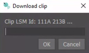
Send a clip to EVS
Options:
- Right click on a clip thumbnail in ClipStore and select Send to device. Type the destination LSM ID into the pop up window and click OK. Make sure the given LSM ID is available in Multicam.
- Autotransfer: Create any telestration on the video shown in the Tactic video window and initiate a layoff. In this case the filename of the layoff will have to be an LSM ID only. The id format is Page, Bank, Clip numbers followed by the Cam letter without space: 111A . Lower case is accepted. The layoff file will be named accordingly in the Tactic layoff folder with a timestamp and extension, e.g: 121A_18-40-51.mxf
Send from clipstore:
Autotransfer:
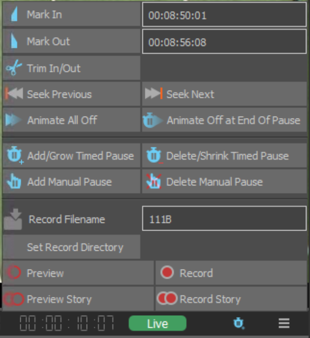
VT Device
Plugin Name: Default is FileClipStore. Select the VT (clip) source, for local clips in RTSW/Clips, use “FileClipStore”.
Pause Delay: Default setting is 2 frames. Adjust this if you find that when playing the video clip it does not pause at the selected timecode once analysis graphics have been added.
Play Delay: Default setting is 2 frames.
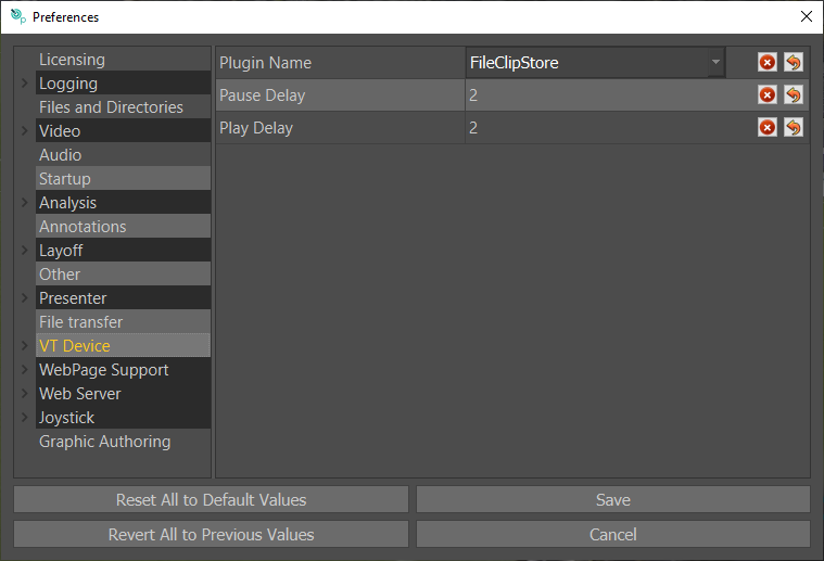
Speed Control
These parameters define the scrolling behaviour in Tactic. Speeds can be increased by increasing the parameter’s value.
Fast Forward Speed: Default 1.0
Jog Speed: Default 1.0
Shuttle Speed: Default 1.0
Slow Step Speed: Default 0.5
Fast Step Speed: Default 1.0
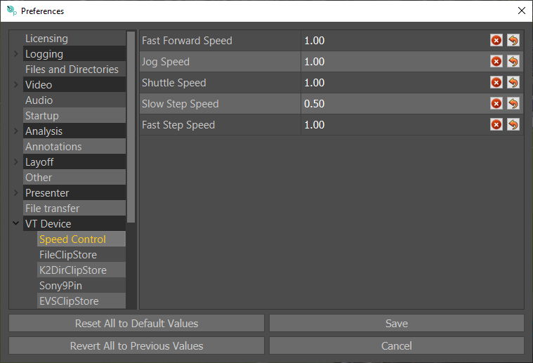
FileClipStore
Clip Directory: Set this to the file path of the base directory for your clips.
e.g. DesktopRTSWclips
Automatic Updates: Set this to automatically update the thumbnails in the Clip Browser.
Upscale/Downscale Filter: When using file based clips, these filters determine how video gets scaled if you feed a different video input than expected.
Different filters have different performance effects and have visually different results. Experiment with the scaling filter to find the one that suits your needs best.
Deinterlacing : The method used to convert interlaced video clips.
Use TC Offset: Enable this to use Time Code Offset. With this enabled Tactic will offset real time timecodes sometimes used with MOVs and MXFs.
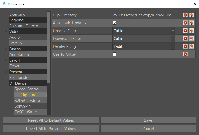
K2DirClipStore
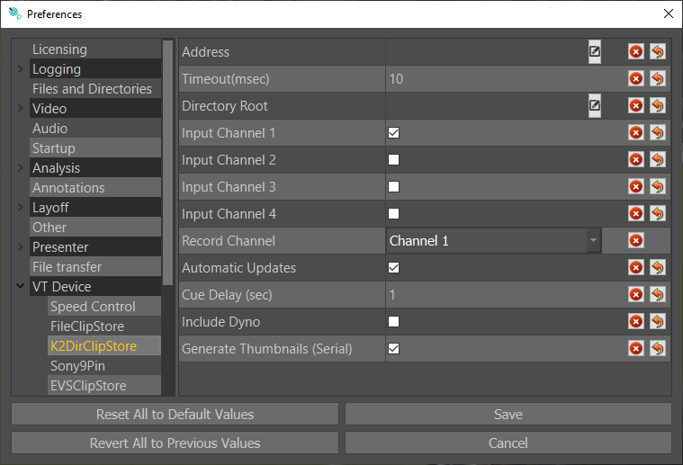
Address: Set to the network address of the control port of the K2. This is a standard IP address or hostname. E.G.: 192.168.10.10, or K2Control.
NOTE: Based on the entry address typed here, Tactic will determine whether to use network or serial connection. Setting the address to tty… or COM… will select serial control. An IP address will select network connection.
Timeout: In case of serial control it indicates the timeout on trying to send a command to the K2 before an error returns on failure.
Directory Root: Type in a file path to limit which directories on the K2 will be searched and made available. For example, default/steve/tmp would only look inside of the “tmp” directory on the K2.
Input Channel 1-4: Tick the boxes next to the channels that Tactic will control on the K2 server. The corresponding channel selector buttons will become available on the VT Control section.
Record Channel: When using the Record functionality, this defines which channel of the device to control for recording clips.
Automatic updates: Turn on automatic update if you want Tactic to automatically update its list in sync with the VT device. Clip changes on the VT device will be reported from a known sentinel point such as a refresh. If you delete or add clips these changes will automatically update the Tactic Clip window.
NOTE: Network connection is preferred to serial connection because the network is faster and the serial does not support auto thumbnail creation.
Sony9Pin
The Sony9Pin (BVW75) clip plugin provides VT control via serial connection over any video device that supports this protocol. Tactic has been qualified with major brands such as K2, EVS, Sony Digital Betacam and Doremi.
Tactic preferences
VT Device: This setting defines how the System responds to some of the controls. It especially affects how the eject button works.
Seeking Method: This defines which Sony command is used for clip seek. If you are experiencing problems with seeking on clip restart you may find that changing this setting helps. This is especially true for VT Decks.
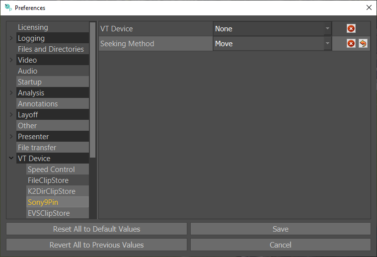
EVS configuration for the Sony9Pin plugin
This section describes how to set up an EVS Video Server for Sony9Pin control under Tactic. Although the EVS configuration is outside the remit of this document a brief outline is provided here to assist operators in setting up and troubleshooting the system.
NOTE: these settings were correct at time of writing, but if the EVS workflow has changed since then they may not be correct – consult the relevant technical studio/broadcast staff to check.
The control protocol used is Sony BVW75 (9 Pin) that allows simultaneous control of the EVS between Tactic and the LSM Remote controller.
The EVS is connected by a straight-through pin-to-pin RS422 serial cable to a serial extension panel of the Video Board on the Tactic PC.
EVS Setup via LSM
LSM Remote Main page
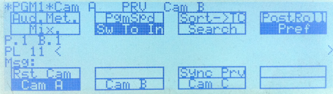
- From the Main system menu (Shift+Menu) select Technical Setup (press F10). Then use F10 to advance pages and F9 to go backwards in the Technical Setup menu.
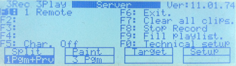
- Find page T2.2 – as indicated in the top right corner of the screen and set by pressing F2 and then using the Jog Wheel to select SonyBvw75 from a list of available protocols:
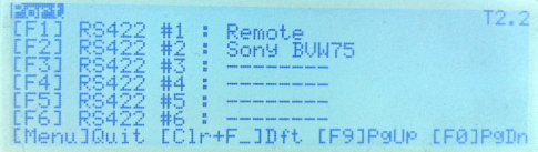
- Advance to page T2.3 and set SonyBvw75 as a secondary controller.
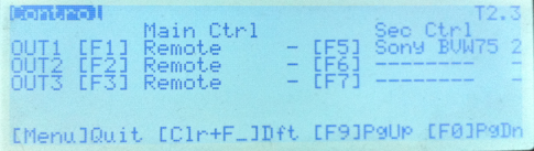
- Go to page T2.5 where you can set SonyBvw75 to parallel or exclusive.
- When finished press Menu to quit the setup and the system will prompt to save which is necessary in order to apply these changes.
EVSClipStore
This plugin provides control over clips stored on an EVS using the Odetics protocol through serial RS422 connection to a generic serial port on the Tactic machine. Video streams are delivered over SDI.
Setup basics
- Connect an RS422 port on the EVS to the COM port of the Tactic PC. For RS232 ports an RS422 to RS232 adapter is required.
- Assign that EVS port to Odetics on the EVS.
- Select Odetics as a main or secondary controller on an EVS video OUT channel that will output to Tactic.
- In Tactic Preferences on the VT Device page select EVSClipstore.
- In preferences on the EVSClipStore page select the serial device. This is usually “COM1”, check Windows Device manager if you have multiple COM Ports.
- Set EVS Net ID (default is 0, for using one EVS only)
- In EVSClipStore preferences set bank, page and cam filters to determine which set of clips will appear in the Tactic cliplist.
See further configuration and parameter details below.
NOTE: The EVS must be configured to output VITC time code and Tactic Timecode Type must be set to VITC on the Video preferences page.
Tactic configuration for EVS Odetics
Serial Device: Set to the PC serial port that is connected to the EVS. This is usually COM1.
Use Thumbnail Bank: This option has two features:
- Sorting clips into separate directories according to Keywords that are set for clips on the server side.
- Selecting a specific video frame from which the thumbnail will be made. See the Use Thumbnail Bank section below.
Generate Thumbnails: deselect this in case no thumbnails are needed.
Thumbnail Delay: Used in thumbnail creation. Set the delay between EVS starting to load a clip and Tactic grabbing the thumbnail. That is in case it takes too long for the EVS to load a clip before a frame is grabbed from the video input.
Page Filter: Include only these page numbers (0-9) when updating the clip list.
Bank Filter: Include only these bank numbers (1-9) when updating the clip list.
Cam Filter: Include only these camera inputs (A-F) when updating the clip list.
EVS Net ID: This will be 0 if the EVS server to which Tactic is connected is the very same server that Tactic needs to control.
If the EVS server of interest is NOT the one physically connected to Tactic but one on its network of servers, then set the target EVS server Net ID (1-99).
Please see the EVS documentation for further explanation on EVS server networks.
EVS Total Recording Trains: Specify how many record channels previously configured on the EVS you wish to be available.
Creating Thumbnails
The EVSClipStore plugin uses the SDI video input signal of Tactic to make thumbnails for the clips in the built clip list. For this it loads each clip on the EVS one after the other on whichever PGM channel Odetics is configured. If Use Thumbnail Bank is selected then only specific clips will load. Read the Use Thumbnail Bank section for more details.
NOTE: make sure that this process will not interrupt your production.
Use Thumbnail Bank
In this mode when the clips are prepared, the operator should clear all clips from other channels and save the clips on Cam A. They should then make a single frame clip from the clip on Cam A, and save it to the corresponding Page and Bank number on Cam B. This clip will be the thumbnail clip and it will only be used to generate the thumbnail.
E.G.: supposing there is a clip with ID 133A/00 the thumbnail MUST exist on 133B/00.
NOTE:
- Make sure that the Cam Filter settings exclude the channels where the thumbnail clips are stored. (Cam B usually)
- It is actually not restricted which channel to use for thumbnails and clips. Tactic will always look for a clip with the matching Page and Bank number on the channel consecutive to the selected clip’s channel: A->B, B->C, C->D,…
EVS configuration for the EVSClipStore plugin
Video connection
The EVS server provides VT source material via the SDI input to the Tactic system. The installed video board is likely equipped with several i/o BNC connectors and input-1 is where the selected channel on the EVS should be connected. The Output socket provides HD SDI output for Tx. This combines the EVS input with telestration. The Ref input is not used since Tactic is synced to its SDI input.
Serial connection for VT Control
The second connection between the EVS and the Tactic system is the RS422 Serial control feed. The serial connection is a straight thru cable and may be extended via CatV at the Studio panel or via fibre. The port on the EVS should be on the same channel as the EVS video output.
The Serial cable is terminated at the PC through an RS422/232 converter to the serial port, usually COM1. The converter is vital and correct operation will not occur if it is omitted. Ensure it is connected the correct way round with the 422-end plugged into the cable going to the EVS and the 232-end plugged into the computer.
The final stage in EVS configuration is the setup of Odetics protocol on the EVS.
Exclusive and parallel modes
The Odetics protocol can be used in three different modes on the EVS:
- Odetics being set as a Main Controller on a PGM channel. No other controllers including the LSM can access that channel.
- Odetics being set as a Secondary Controller in Exclusive mode. Both the main (LSM) and secondary (Odetics) controllers receive permanently the status of the channel(s), but only one controller at a time is able to actually control the channel. The main controller can decide at any time to pass the control to, or to retrieve the control from the secondary controller.
- Odetics being set as a Secondary Controller in Parallel mode. Both the main (LSM) and secondary (Odetics) controllers receive permanently the status of the channel(s), and both controllers are able to control the same channel at any time. Either of both controllers can take the control as long as the other controller is not executing a command. The control can thus be freely passed on from one controller to the other.
The following sections describe how to set all this up on the LSM Remote’s user interface.
LSM setup on Multicam 16
The following is a working example on how to use Odetics with Tactic through a RS422 serial connection.
In this example, on all the EVS channels the LSM Remote is set as the main controller and Odetics is set as a secondary controller in parallel mode on channel PGM1. The serial cable is plugged into RS422 #2 connector on the server.
- From the Main system menu (Shift+Menu) select Technical Setup (press F10). Then use F10 to advance pages and F9 to go backwards in the Technical Setup menu.
- Find page T2.2 – as indicated in the top right corner of the screen and set by pressing F2 and then using the Jog Wheel to select Odetics from a list of available protocols:
- Advance to page T2.3 and set Odetics as a secondary controller.
- Go to page T2.5 where you can set Odetics to parallel or exclusive.
- Press Menu to quit the setup and save the changes when the system prompts to.
EVSLinX
Overview
The EVSLinX plugin is used to access and control clips stored on an EVS video server. Using the LinX protocol over network Tactic can control program and recording channels. Video streams are delivered over SDI.
Main features
- Full Tactic VT control on up to 2 PGM channels on the EVS using LinX as a Main Controller.
- Monitor any two of the Recording trains in E2E mode on two separate Tactic input channels.
- Full Tactic VT control on any of the recording trains.
- Record back to an EVS recording train in real time including Tactic graphics and clip creation.
- Create a clip list with thumbnails in Tactic. Thumbnails are grabbed from the SDI input while clips are loaded in a sequence.
- Auto update Tactic’s clip list in response to new clip creation and clip changes made on the EVS.
NOTE: EVS only supports LinX on Windows operating systems.
Connections
In a typical configuration the connections and work-flow between Tactic and the EVS server would be as follows:
Network connections
EVS Pc LAN socket → main Ethernet Network.
Tactic PC network socket → main Ethernet Network.
Video SDI connections
EVS OUT-2 → TACTIC IN-1
TACTIC OUT-1 → EVS IN-1
In this configuration Tactic can control one PGM channel on the EVS while monitoring it on the video input. Build its own customised clip list based on id filtering preferences from the clips that exist on the EVS server and create thumbnails for them by grabbing one frame of each clip.
After building an analysis sequence in Tactic the clip can be recorded back on to the EVS with the overlaid graphics, then Tactic will make a clip on the server at the specified time codes.
Network connections on the Tactic PC
LinX
The LinX protocol controls the EVS channels and connects to the PC LAN socket on the server.
Local IP setting
If there are more than one physical, active network connection on the Tactic PC on the same subnet to the EVS network then it is possible that LinX cannot reliably detect which local connection to use. In this situation you can set the Local IP address in the Preferences menu to avoid this. This is the IP address assigned to the network port that connects to the EVS. Check the Windows network settings.
It is recommended, however, that 2 different subnets are used for the 2 connections.
EVS configuration for LinX
This section will explain how to set up a working configuration for LinX by using the EVS Multicam 16 software interface. See the EVS documentation for further details.
- Open up the main configuration window.
This is the main window that appears after the EVS has started up. If the Multicam is at the clip list view then you must exit by either pressing ALT+Q or by using the LSM Remote.
Network connections
- To set the PC LAN port IP address:
- Select a configuration line at the left side of the setup window
- Press L and use TAB to navigate the menu
- Disable DHCP
- Set the IP address, Subnet and Default gateway
- Press ENTER to apply
Main configuration window on EVS from Multicam 16:
Setting up channels for LinX
- To set the channel configuration on the EVS:
- Select a configuration line under the setup window
- Press F8 then F3 for Advanced Mode
- Navigate to the CHANNEL window by pressing the RIGHT arrow
- Press TAB several times to navigate to the required line
- Set Base config to Multicam LSM.
- Press PageDown for the 2nd page and TAB to select the RS422 ports
- Set one of the RS422 ports to LinX.(This port and channel will be used exclusively by LinX)
- Set LinX as a Main controller on one or two OUT channels depending on how many channels Tactic will need to control.
NOTE: in Multicam LSM mode PGM1 and RS422 #1 has to be set to EVS Remote.
- When finished press ALT+A to apply
CHANNELS configuration windows on EVS from Multicam 16
Page 1:
Page 2:
Setup Tactic for LinX
To open the EVSLinX plugin open preferences and in the “VT Device” section select Linx. Then, expand the VT Device folder in preferences and go to the LinX page (see screenshot below). Set the LinX and Local IP.
If there are lots of clips on the EVS, it is recommended to to disable thumbnails so the clip list will refresh faster.
Set your EVS ID, in cases where you have only one EVS on the local network set this to 0, otherwise use the EVS ID the EVS is assigned too.
Set record channel 1 to whatever channel you have assigned LinX to on the EVS. If you are using a second channel in Tactic and have a second video in from the EVS, this should be set to the second channel LinX is assigned too. The Record channel is the output of Tactic going back to the EVS, set this to whichever channel is assigned to recording the Tactic return on the EVS.
It is recommended to use VITC timecode (see video preferences in Tactic) for most use cases.
This is the core set up for EVS Linx, however it is common to use bank, page and cam filters so only the clips in your designated bank/page on the EVS appear on the Tactic cliplist. See below for details on all LinX parameters in Tactic.
Opening EVSLinX plugin for the first time
On selection of the EVSLinX plugin for the first time after installing Tactic the plugin will not be initialized correctly. The first item to set is the LinX IP address of the EVS server. See the EVS Configuration for LinX section to determine this address.
Once the LinX IP is set LinX will try to re-initialize and if successful Windows will prompt to allow network connection to the EVS server. This will have to be authorized through a Windows pop-up dialogue.
Until LinX is configured correctly Tactic will repeatedly attempt to open the communication channels used to communicate with the EVS. This will result in various error messages appearing on the Tactic debug window until successful connection . See LinX debug output for further details.
EVSLinX setup via Tactic preferences / VT Device / EVSLinX:
LinX IP: PC LAN connection IP address set on the EVS server for LinX.
Local IP: This has to be set if there are more than one active network ports on the Tactic PC. Set this to the IP address of the network port that is connected to the same network as the PC LAN port on the EVS.
Clip folders: Thumbnails will be organized into directories according to the assigned EVS keywords in the clip.
Thumbnail Delay: The delay between requesting a thumbnail and grabbing it from video in. When thumbnails are grabbed from SDI input after being brought to air on the EVS this delay is the period of time that the plugin will wait before capturing video from the input.
Rec Train Delay: Optional delay to give time to EVS to switch to a LIVE channel when loading a recording train from the clip list or when loading an analysis before another event happens. This might be 0 depending on the usage and circumstances.
Generate Thumbnails:
- All Clips: make a thumbnail for every clip in the built clip list.
- New Clips Only: going through the clip list for each clip Tactic looks for a matching thumbnail file of the correct format in the Thumbnails directory. For every file that is missing, Tactic will grab a thumbnail.
- No: no thumbnails will be transferred. Tactic will still look for existing thumbnails in the Thumbnails folder and use them or set a default blank thumbnail for the clip.
Page Filter: Include only these page numbers (0-9) when updating the clip list.
Bank Filter: Include only these bank numbers (1-9) when updating the clip list.
Cam Filter: Include only these camera inputs (A-F) when updating the clip list.
Input Channel 1: Set EVS OUT channel (1-6) that is connected to Tactic video IN 1.
Input Channel 2: Set EVS OUT channel (1-6) that is connected to Tactic video IN 2.
Recording channel: Set EVS recording train (1-6) on which Tactic output will be recorded (via SDI) for creating clips, locally or by Tactic.
EVS Net ID: This will be 0 if the EVS server to which Tactic is connected is the very same server that Tactic needs to control.
If the EVS server of interest is NOT the one physically connected to Tactic but one on its network of servers then set the target EVS server Net ID (1-99).
Please see the EVS documentation for further explanation on EVS server networks.
Automatic Updates: Default to false. Automatically update Tactic clip list with changes made on the EVS regarding add/remove/rename clips.
Show OSD: Outputs text information on Linx channels the same way the Main channel does (on LSM Remote). Clip name, Timecode, etc..
Using the EVSLinX plugin
Build clip list
Clip list is always built and updated based on the Page, Bank, Cam filter settings in preferences.
To import the clip list, click on the Refresh Clips icon
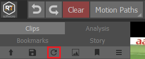
EVSLinX debug output
Successfully initialized LinX with 2 PGM channels and one recording channel. LinX is configured to control through RS422 port-4 on the EVS.
———————————————————————————————————-
Channel connection error
“LinX – A player channel must be set to load clips. Set Input Channel 1 or 2 to the configured LinX port.”
– No channels are set on both Input channel 1 and 2.
———————————————————————————————————-
“LinX – connecting EVS-OUT1 -> PC-IN1 failed.”
“LinX – connecting EVS-OUT4 -> PC-IN2 failed. Error: Error during open access”
– Channels settings are incorrect. Failed to connect EVS PGM1 and PGM4 to Tactic. Check EVS configuration whether LinX is set to control these channels or change Input channel 1 and 2 to different EVS channels.
———————————————————————————————————-
Time code error
“LinX – Failed to get time code Error: Bad channel type”
1) Didn’t set Input channel 1 and 2.
2) Only either Input channel 1 OR 2 is set correctly but the VT Control channel selector is on the wrong channel.
———————————————————————————————————-
Lost network connection
“LinX – Failed to get timecode Error: A time-out occurred”
“LinX – Lost IP connection. Error: Connect error. Trying to re-open EVSLinX plugin.”
“LinX – IP connection failed. Error: A time-out occurred”
– All these messages suggest that you have lost the network connection to the EVS. If the error message keeps appearing in a constant rate it means your connection is permanently off.
Every time the connection is lost Tactic will try to re-initialize the plugin.
———————————————————————————————————-
“LinX – Database connection failed.”
“LinX – Syncing Database failed.”
– When the database connection or synchronization fails but the IP connection is fine it means the database management was busy at the time and Tactic will try to re-open the connections.
EVSClipStore vs EVSLinX
This table collects the main technical differences between EVSClipStore and EVSLinX plugins. This is to help decide which plugin may work better for a particular production.
| EVSClipStore | EVSLinX | |
| Connections | ||
| Tactic control over EVS | serial cable + rs422 converter or USB-Rs422 | LAN via main Ethernet network |
| Tactic video I/O | SDI via video I/O boards | SDI via video I/O boards |
| Clip thumbnail transfer to Tactic | via SDI | via SDI |
| EVS setup | ||
| EVS channel occupation | can be set as a secondary controller on any EVS player channels, working in parallel with an LSM control. | Needs to occupy a whole EVS channel, taking exclusive control over it.
(This is under review by EVS) |
| Compatibility | Requires Odetics protocol being available on the server. It’s an old protocol so very much available and compatible to old servers and Multicam too. | – requires Multicam 11.47 +
– requires network Multicasting capabilities for Clip List Auto Update |
| Tactic Features | ||
| Making clips from Tactic output onto EVS (record+clip) | only manually via LSM | via Tactic interface with precise TC |
| Clip List Auto Update | no support | Tactic Clip List is managed by a regularly synced database. Any changes made on the EVS will appear in Tactic too. |
| Clip List thumbnails | Requires exclusive control over one EVS channel, temporarily.
For every thumbnail: – Tactic loads a clip on EVS – records the first frame onto disk via SDI input – scales the picture to thumbnail size – Takes 1-1.5 sec each |
Same as EVSClipStore |
K2 DLC
System Overview
This guide is to provide system operators, support staff, and engineers in the setup, configuration and operation of the K2 Video Server using DLC (Distributed Lan Client) to provide clip information for Tactic direct from a K2 Summit/Solo or San system. The connection between the Tactic system and K2 is network based and utilises a DLC client/server mechanism called Storenext by Quantum. The diagram below illustrates the system architecture.
K2 DLC System Architecture
The principle behind the connection is basic file sharing. The media drive on the K2 is shared and is mounted onto the Tactic system. The DLC client provides a file system called CVFS or SNFS to allow this to be done.
Requirements and Warnings
There are a number of requirements to allow network mounted clip playback using SNFS/DLC. These are
- SNFS/DLC with the K2 is not guaranteed to be real time in all situations. There is a finite amount of bandwidth available on the K2 and if this is being shared with SAN backup, DynoPA, Proxy control then your playback may not be in real time. You can still play and record back to the DLC and the completed clips will be real time. But if you are trying to play direct to air you should fully test your K2/Tactic setup beforehand.
- Ensure you have JumboFrame support enabled on your network NIC’s If you do not you will not get the optimum performance and you will increase the chance of dropping frames.
- Ensure you have Reference clips enabled on the K2. Otherwise, all clips without reference mov files will appear as directories in Tactic.
- Ensure you are using the correct version of the SNFS Client for the K2 you are connecting to. RTSoftware does not supply the SNFS Client for this feature. If you require this then you should contact either GrassValley or Quantum.
Connection
The connection between the K2 and the Tactic system relies on a 1Gb network link. The network connections assume that network access is configured on both systems. It will also depend on whether you are running a DHCP server or not. If you are not running DHCP you will have to manually assign an IP address to the Tactic system.
The network cable should be connected to the Tactic system using the lower of the 2 network ports on the back of the machine (usually labelled ASF). You should have been supplied with a DLC.zip file that contains installers for Windows. It also contains this document as well as other docs for Windows configuration.
Windows Installation and Configuration
This guide does not cover the installation of the DLC client for Windows systems. This is extensively covered in the DynoPA system guide – PA_v2.0_ConfigMan.pdf
You will find this in the DLC.zip you should have obtained. The docs and installers are located in the Windows directory of the zip file.
Troubleshooting the K2 DLC
If you cannot successfully connect to the K2 you should check that the K2 is configured correctly. Check the following
- Ensure you have entered the correct information into the Tactic system configurations files
- Can you ping the K2 Open a Dos and type
ping <hostname of IP address>
The K2 should respond:
64 bytes from k2control.rtsw.co.uk (192.168.100.81): icmp_seq=1 ttl=128 time=0.090 ms
- Is DLC enabled and running on the K2? On the K2 desktop, goto System->All Programs->GrassValley->DLC Config->Launch DLC Tool.
If this is not there then DLC has not been installed. If it is, run it and check that DLC is running. If DLC is not running consult GV docs on how to start.
- Is the correct nameserver IP address entered? Run AllPrograms->StoreNext FileSystem->NameServers. The IP Address of The K2 should be configured. If it is wrong, delete the entry and type in the correct one. Note that you will need to disable the Write Filter to make permanent changes thru reboots. Check K2 docs for more info.
- Is the Name binding correct? Open up the Network Setting dialogue.
Open up Network connections on the K2. Select ‘Advanced Settings’ from the Advanced menu at the top of the dialogue.
- Ensure that the ‘Control Team’ is at the top of the binding list and that ‘Loopback Adapter’ is at the bottom. Use the arrow keys at the side to change.
LiveTouch
Live Touch IP Address: Default is Blank. The IP of the LiveTouch server
Network Port: Default is “80”. The PC network port to connect to the LiveTouch server.
Live Machine Port 0: Default is “0”.
Live Machine Port 1: Default is “0”.
Live Machine Port 2: Default is “0”.
Live Machine Port 3: Default is “0”.
Auto Update: Default is unticked. When ticked Tactic will automatically update changes from the LiveTouch server.
Category: Default is “togsports”.
PlaylistName: Default is “togplaylist”.
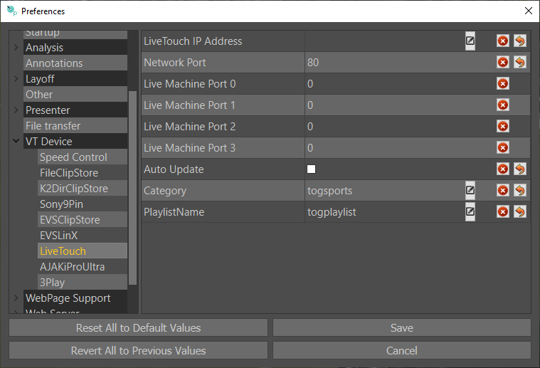
AJAKiProUltra
AJA IP Address / Hostname: Default is Blank. The IP/Hostname of the AJA IP host server.
Thumbnail Delay (secs): Default is “2”. The delay between requesting a thumbnail and grabbing it from the video input. This is to provide enough time for the server to receive the request and load the clip.
Skip Wrong format: Default is unticked. This skips clips that are not the format selected in the Tactic video settings.
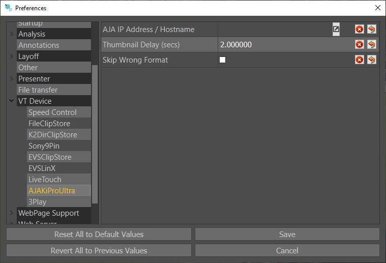
3Play
3Play Address is for the IP address of the 3Play server.
Output Channel Defaults to 0. This selects the output channel used on the 3Play Machine.
Clip Directory is the path to the 3Play drive. This should be mounted as a network share on the PC. See Mounting a Network drive on Windows 10 for details.
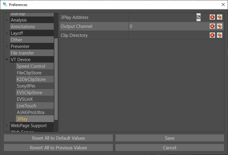
Mounting a Network drive on Windows 10
To mount a network drive on Windows 10, first navigate to “This PC” in Explorer. Then Select the “Computer” tab and select “Map Network Drive”.
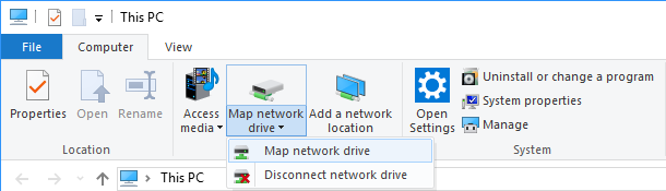
In this example X: has been used for the drive letter and the IP address of the NewTek system is \192.168.100.199 and select Browse.
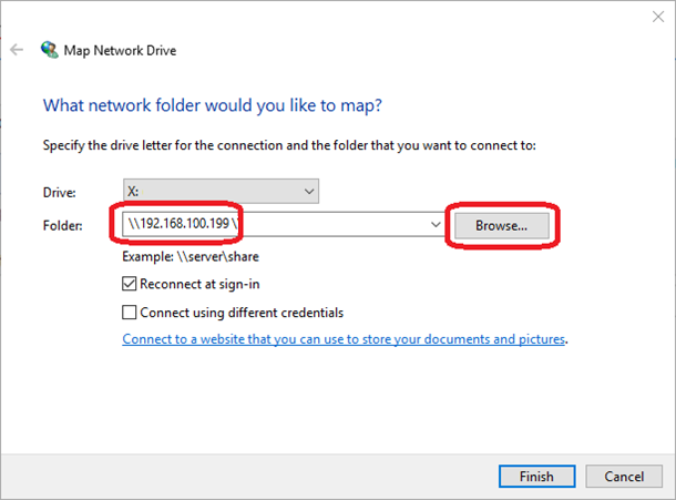
Expand the folder tree and select your clip folder.
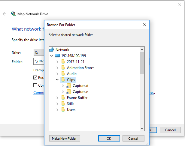
You can now navigate to this folder in explorer from “This PC” and obtain your clips directory for Tactic.
WebPage Support
In WebPage support there are the settings for the web control (tablet interface). The “Cef Home Page” is the first page you will see when hitting the “Web” button.
A sting is an animation or transition which will appear when loading Web or Clips, these can be enabled/disabled here.
Cef Home Page: Default: www.google.co.uk Defines your home page when you hit the Web Button.
Cef Cache Directory: Default $RTSW/Cache Defines the directory where Cef (browser) will cache data. This should not change with normal use.
Use sting on Web Navigate: Default Unticked. When enabled, Tactic will use a Sting while the web page is loading.
Use Sting on Clip Load: Default ticked. When enabled, Tactic will use a Sting while a clip is loading.
Delay before page displayed: Default is 0.5
Take off Delay on Sting (secs): Default is 0.5. This defines the duration of additional time the sting will remain active after the take off has completed, in seconds.
Clip Load Delay (secs): Default 1.0. This defines the duration of additional time the sting will remain active after the clip load has completed, in seconds.
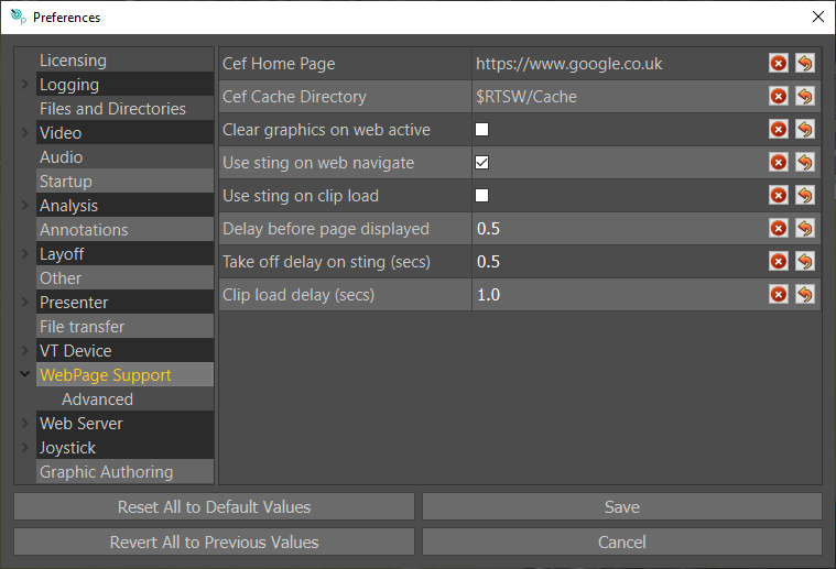
In the Advanced subwindow you enable GPU Acceleration, this will give better web performance for systems running dedicated GPUs. It is only advised to use this on a system which has a dedicated GPU.
The Cef Directory allows the use of specific versions of Cef, this should be left at default for normal users.
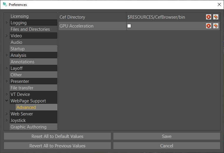
Web Server
Resource Path: Default is $RESOURCES/skins/TacticWebSkin. This can be changed to select between custom and the default Tactic Web skin.
Web Server Port: Default is 80. This is the network port the web server will operate on.
Clip View Type: Default is “Playlist”. This defines what clips will appear in the web interface clip panel.
Default Web Page: Default is “Presenter”.
Clear on Play: Default is checked. When ticked, all graphics laid down in the presenter interface will be cleared when the play button is pressed.
Clear all Graphics: Default is unchecked. When checked this will clear (hide) all graphics made in the main edit window in the web view (tablet mode).

Layout
Clip List Position: Default Left. The Clip List Position defines where the clip list (or burger menu to open it) will be placed on the Tactic Web Interface. It may be placed left or right.
VT Controls Position: Default Left. Defines where the VT Controls (rewind, play, pause and so on) will be placed on the Tactic Web interface.
Show Web Button: Default is unticked. When ticked a web button will be present on the Tactic Web Interface. When pressed it will open the Tactic built in web browser.
Show Live and Channel Buttons: Default is unticked. When enabled a live button will be present in the Tactic Web interface in the burger menu. When clicked Tactic will switch to the live video in.
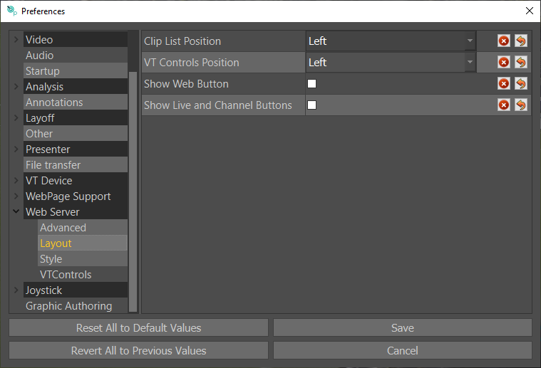
Style
Allows you to change the colours of elements in the web interface.
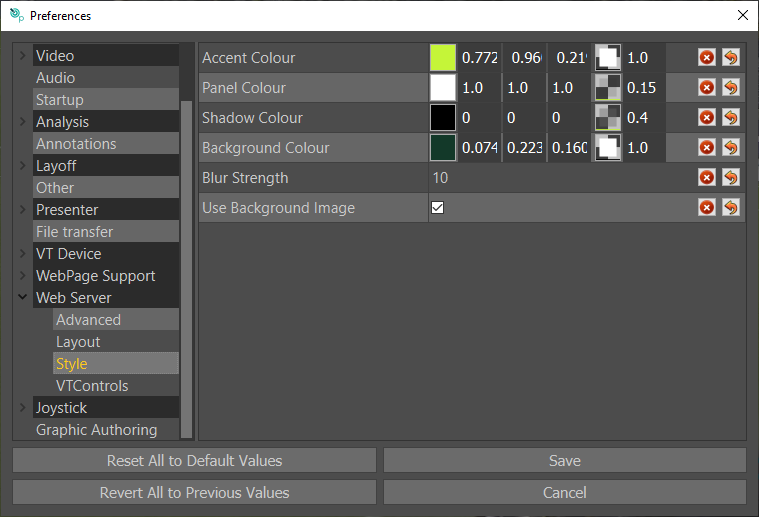
VT Controls
In the Tactic Web Interface there are three slow-motion buttons with varying speeds. By default these are 0.75, 0.50, 0.25. These can be changed in this menu. 1.0 is 100% playback speed, 0.50 is 50% playback speed.
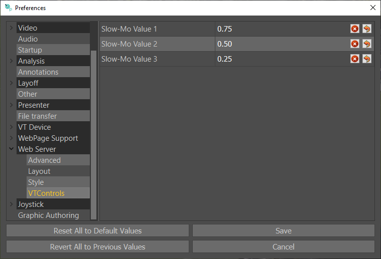
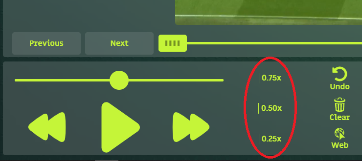
Joystick
When using a Contour Shuttle, select which model you have here.
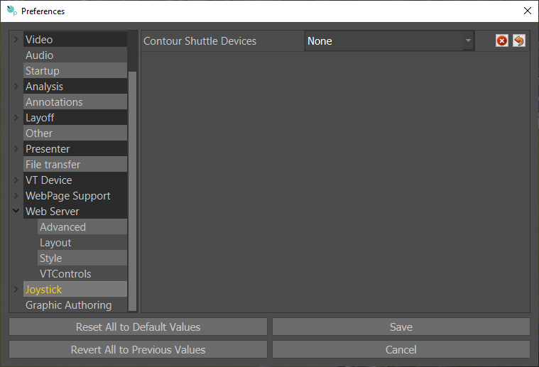
Axis Mappings
To use this a contour must be selected in the “Joystick” menu. Here you can button map the shuttle and adjust the sensitivity of the wheel.
Button Mappings
To use this a contour must be selected in the “Joystick” menu. Here you can button map the shuttle.
Graphic Authoring
Always Reload Scripts: Default is unticked. When enabled scripts will always reload from disk when a graphic is run. This is slower, but means you can edit scripts and see the results without restarting Tactic.
Appendix B – Keyboard Shortcuts
“Esc” Cancel Selected Graphic
“F5” Presenter interface
“F6” Refresh Clips listed in the Clip Browser
“F12” Clear Analysis
“1” Camera 1 (Multicam)
“2” Camera 2 (Multicam)
“3” Camera 3 (Multicam)
“4” Camera 4 (Multicam)
“9” Set the In Timecode of the currently selected graphic(s)
“0” Set the Out Timecode of the currently selected graphic(s)
“-“ Copy Previous Keyframe
“=” Copy Next Keyframe
“W” Select next player in Camera morph
“E” Toggle Erase mode in player cleanup
“R” Animates out the currently selected graphics at the end of the current pause.
If no pause exists, one is created.
“T” Trim automatically sets the Mark In and Mark Out Timecodes to before (pre-roll) and after (post-roll) the graphics in the timeline.
The pre-roll and post-roll times are configurable in Preferences > Analysis
“I” Mark In
“CTRL + I” Move back Mark in by Pre roll amount.
“O” Mark Out
“P” Preview
“Ctrl” + “P” Record
“[“ Previous Keyframe / Event/Adjust brush size and hardness
“]” Next Keyframe / Event/Adjust brush size and hardness
“A” Select linked Graphics /Select previous Player channel in camera morph
“S” Previous player in Camera Morph
“Ctrl” + “S” Save Analysis
“Ctrl” + “Shift” + “S” Save Analysis As
“D” Select next player channel in Camera morph.
“F” Edit Splines
“CTRL + G” Jump to specific timecode
“J” VT Play Backward
“Ctrl/ Cmd” + “J” Skip Backwards 1 Second
“K” VT Pause
“L” VT Play Forward
“Ctrl/ Cmd” + “L” Skip Forward 1 Second
“;” Insert Pause
“Ctrl” + “;” Shrink/Delete Timed Pause
“Shift + Left Mouse” Select Multiple Keyframes/Multiple timeline events.
“Ctrl” + “Z” Undo
“Alt +Z” Zoom in on pitch calibration
“X” Remove Keyframe
“C” Copy Current Keyframe
“V” Delete Keyframes between two keyframes.
“B” Swap Splines
“N” Merge Splines
“M” Toggles Motion Paths
“/” Animate Off
“CTRL + Left Mouse click” Pitch calibration undo
“Alt” + Left Mouse Tumble Camera
“Alt” + Middle Mouse Track
“Alt” + Right Mouse Dolly
“Spacebar” Cue Graphic
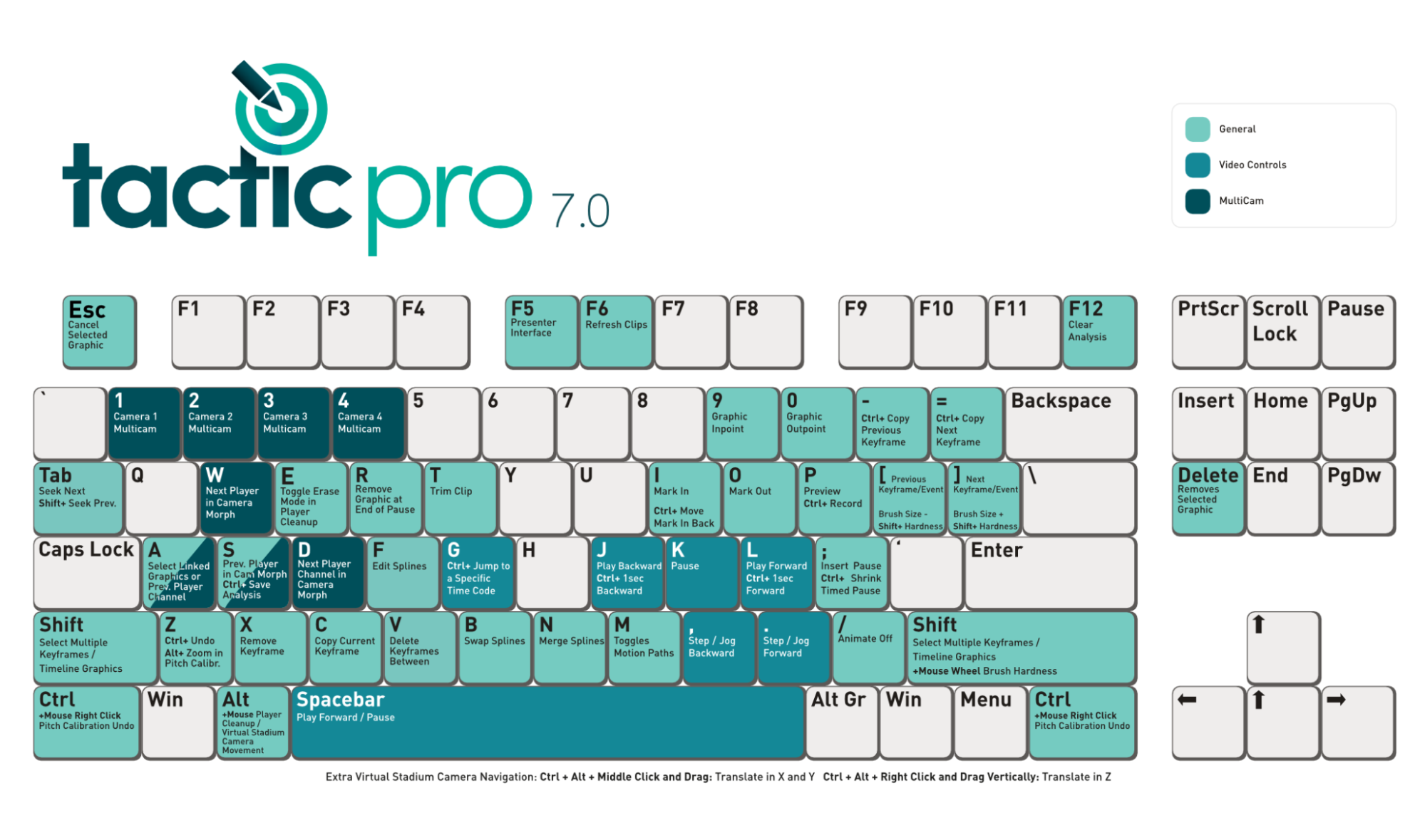
The above image shows current keyboard shortcuts, this can be found in the RTSW/Docs folder on the desktop or, can be accessed from the settings menu:
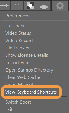
Appendix C – Licensing
License Details
Basic License details such as expiration date and License id is displayed on the splash screen as Tactic starts:
To view more detailed License information, select the “gear” icon in the top right corner and select “Show License Details” …
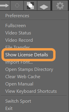
Exact License details will be specific to the version and features of Tactic Pro purchased.
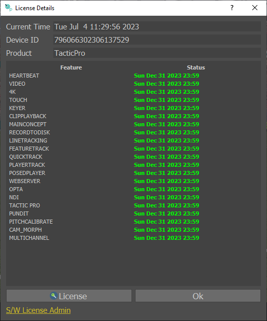
If no License is found the following dialog will be displayed.
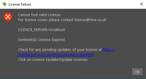
If you already have a License and have been issued an extension, click on the link and follow instructions under “Install a Software License via the Web Portal” later in this section.
If not Click OK to get to the following menu:
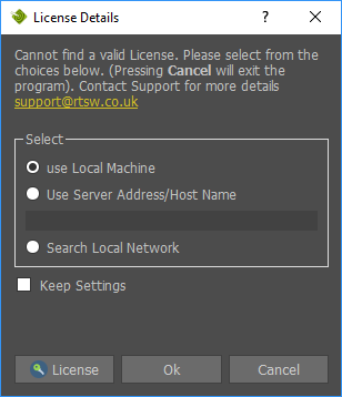
Press “License” to Install / Update a Trial License, Software License or new style USB Security Key.
New style USB Security Key
Install a Trial Software License
A Trial License is available upon request from RT Software https://www.rtsw.co.uk/
To obtain a Trial License, contact sales@rtsw.co.uk
Upon receipt of the Trial License file (TacticPro-30Days.v2c), save the file on your PC in a convenient location and apply the License as follows.
Press “License”
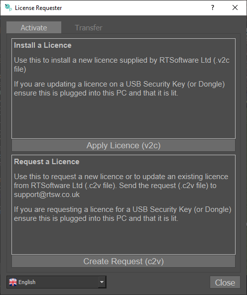
Press “Apply License (v2c)”
Locate and Select the Trial License file (TacticProSP-30Days.v2c)
Request and Install a Software License
A Software License is available upon request from RT Software.
To obtain a Software License, contact sales@rtsw.co.uk
Press “License”
Press “Create Request (c2v)”
Send the request file (Example_0.c2v) to License@rtsw.co.uk
Upon receipt of your new License (e.g.12345678901234567.V2C), save the file on your PC in a convenient location and apply the License.
Press “Apply License (v2c)”
Locate and Select the License file (12345678901234567.v2c)
Update a Software License or USB Security Key
To update your License, contact License@rtsw.co.uk
Press “License”
Press “Create Request (c2v)”
Send the request file (Example_12345678901234567.c2v) to License@rtsw.co.uk
Upon receipt of your new License (e.g.12345678901234567.v2c), save the file on your PC in a convenient location and apply the License.
Press “Apply License (v2c)”
Locate and Select the License file (12345678901234567.v2c)
Transfer a Software License
A Software License may be transferred from an “Old” PC to a “New” PC.
This can be performed at any time without contact with RT Software Ltd.
- Install Tactic Pro on both the “Old” PC and the “New” PC.
- “Collect Info” and create the *.id file on the “New” PC.
- “Transfer License” and create the *.h2h file on the “Old” PC using the *.id file from the “New” PC.
- “Apply License” *.h2h on the “New” PC.
Press “License”
Select the “Transfer” tab.
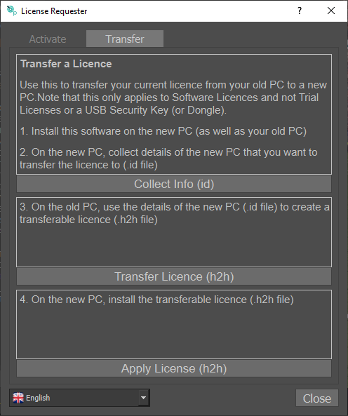
Install a Software License via the Web Portal
If you were provided with a product key instead of a v2c file, please visit https://licensing.rtsw.co.uk/
and copy/paste the key in the appropriate field then hit “Login”.
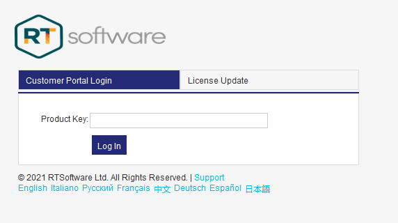
Update a Software License via the Web Portal
Once an update to your License is available, please visit http://licensing.rtsw.co.uk/
And click on the “License Update” tab then click on “Update Licenses”
Appendix D – Importing Fonts
Windows
Select the “gear” icon in the top right corner and select “Import Font” …
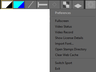
Locate the desired font …
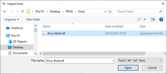
Imported Fonts can be used in any graphic tool that uses text.
e.g.the Info Box
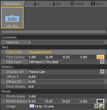
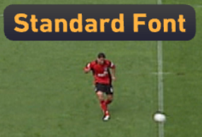
Change the Title Font parameter to the new font …
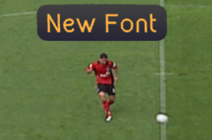
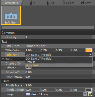
Appendix E – Moving the RTSW Folder
It is recommended to keep the RTSW folder in its default location:
C:Users[USERNAME]DesktopRTSW
However, it is possible to have the RTSW folder in a different location if required. If all your settings are set to default all you need to do is copy your existing RTSW folder from the desktop to your new desired location. Then in preferences under “Files and Directories” there is a “RTSW Directory” setting where you can enter your new directory.
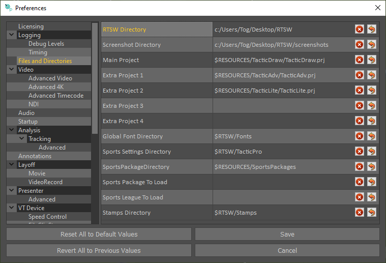
If you have changed any other directories in Tactic preferences, you need to check they are going to the new RTSW directory too.
“$RTSW” denotes the directory specified in the “RTSW Directory” setting. This can be replaced by a full directory if desired.
“$RESOURCES” points to: “C:Program FilesTactic[VERSION]” and should not be changed.
Appendix F – Engineering Notes and Troubleshooting
There are 2 additional manuals that may be useful:
Video
Tactic supports the AJA range of video cards. For further details and video trouble-shooting please see the “AJA Driver Installation” manual.
Contour Shuttle
If you intend to use a Shuttle controller please see the “ShuttleContour Tactic” manual.
System Connectivity
Video
Control
Log Files
Tactic writes diagnostic data to a log file. The default location for the log file is:
C:Program Filestoglog
The location and name of the log file can be specified in the Tactic Preferences menu in the “Logging” section:
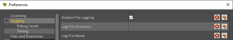
By default Tactic writes useful start-up messages and errors to the log file. Increased logging data can be set in the “Debug Levels section”. Please note that turning on extra debugging can slow Tactic down significantly and so should only be set for testing purposes.
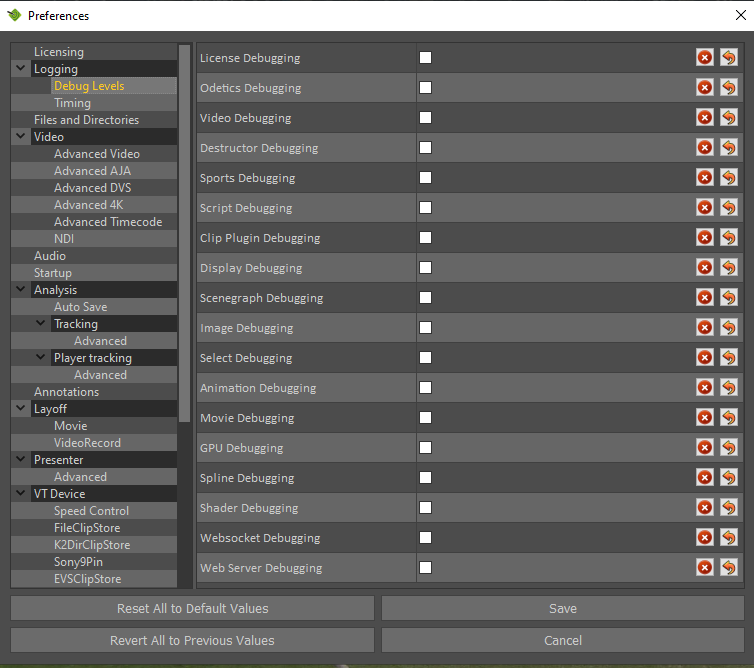
Performance Data
Tactic can also show internal performance data:
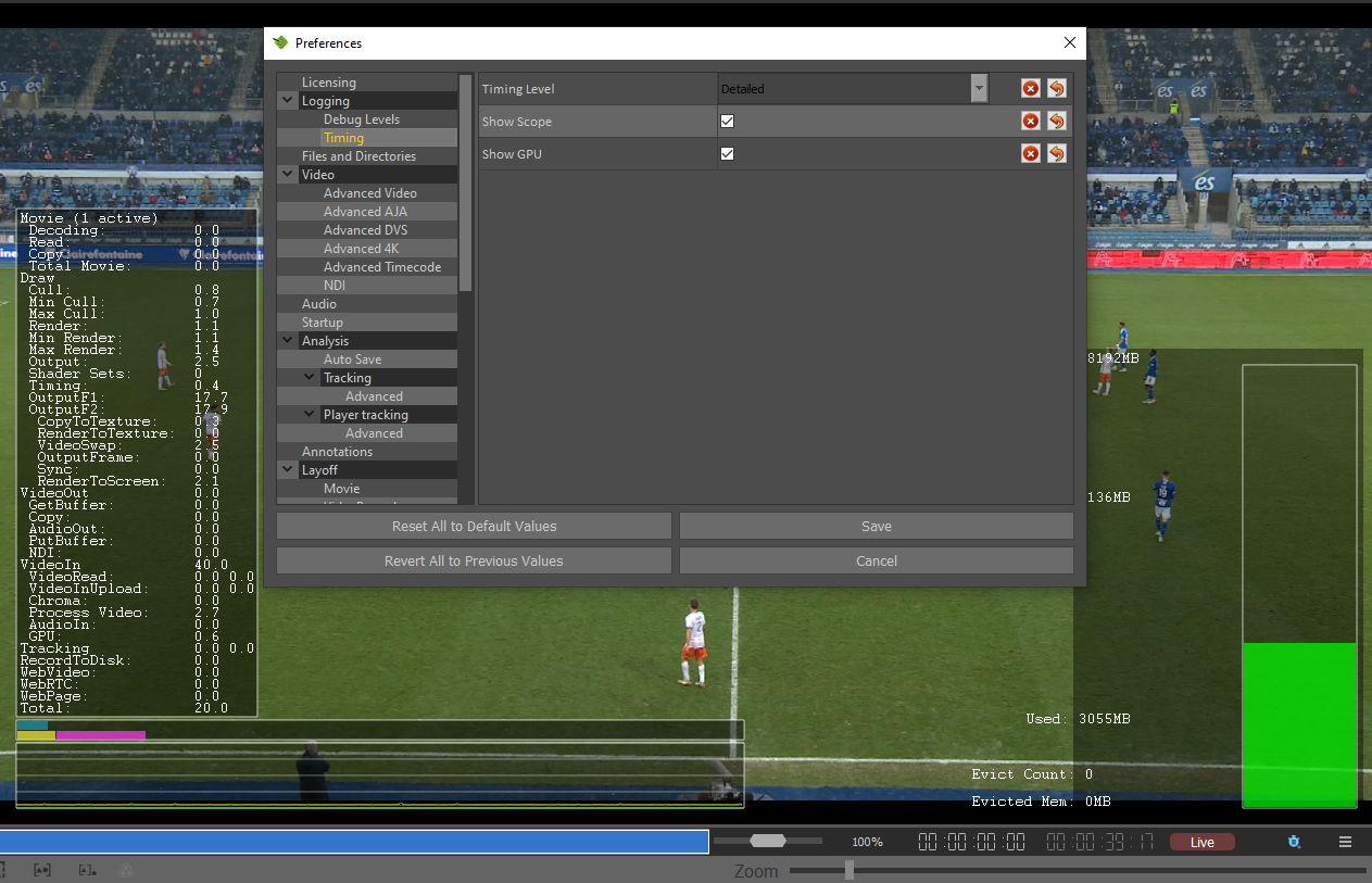
Setting the “Timing Detail” to “Detailed” brings up a column of timing data. The bottom value (Total) should be a constant 20ms (for 50Hz video) or 16.7ms (for 59.94Hz video). This is the total time taken to render a single frame (or field with interlaced video). If it exceeds 20 (or 16.7) then the system is not rendering in real time and the output will judder.
Reporting Problems
Any support problems should be emailed to support@rtsw.co.uk
Please include the full Tactic version and the operating system in your email. In general the more details you can give the better we can diagnose the problem. If appropriate please include the relevant log file.
All emails to support:rtsw.co.uk should be answered within 1 working day and often much sooner including weekends. Please always use “Reply-All” when replying to support emails.