Tactic Clip Plugins
Support literature - Clip Plugins

Support literature
Clip Plugins
|
About |
Description |
|
Revision |
|
|
History |
|
|
Authors |
Clip Plugins
Overview
Device Support
Tactic Advanced and Tactic Pro support the playback of clips from an external device, or from internal clips. Clip support is accomplished through the use of plugin technology.
This allows possible future support for new devices without having to update the main application. It also allows end users to implement their own plugins.
If you wish to write your own plugin then contact RT Software to obtain the plugin SDK.
Tactic products ship with the following plugins:
- FileClipStore, This plugin allows playback of file based clips. It can be used for:
- File based clips from a local hard drive
- File based clips off a suitably fast shared drive.
- K2 Summit support using the SNFS DLC to mount a shared drive. This method does not require an SDI channel.
- It can also be used in conjunction with record to disk functionality to provide near live replay functionality.
- K2DirClipStore, K2 Summit support using SDI for video and Odetics over network for control.
- Sony9Pin (BVW) supports Digibetas, and most other devices that are Sony 9 Pin compatible.
- EVSClipStore, EVS support via the Odetics protocol using serial RS422 connection.
- EVSLinX, EVS support via Ethernet network – only available on Windows.
The following table summarises the supported capabilities on each device.
|
Plugin name |
Device |
Control Type |
SD |
HD |
VT |
Clip |
Thumb |
Rec |
Auto Update |
Requires SDI |
|
FileClipStore |
Internal Clips |
File Based |
Y |
Y |
Y |
Y |
Y |
Y |
Y |
|
|
K2DirClipStore |
Grass Valley K2 |
Network |
Y |
Y |
Y |
Y |
Y |
Y |
Y |
Y |
|
Sony9Pin |
Sony 9 Pin |
Serial |
Y |
Y |
Y |
|||||
|
EVSClipStore |
EVS |
Serial |
Y |
Y |
Y |
Y |
Y |
Y |
||
|
EVSLinX |
EVS |
Network |
Y |
Y |
Y |
Y |
Y |
Y |
Y |
Y |
NOTE: The above table is subject to change, newer versions of Tactic may have more capabilities. Check with your supplier.
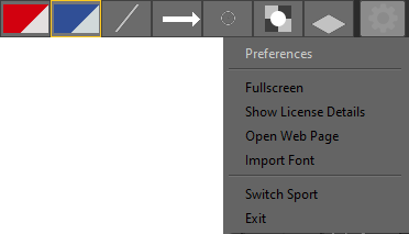
Preferences
Access the Preferences to change the default configuration of Tactic Advanced or Tactic Pro.
Select the “gear” icon in the top right corner and select “Preferences” …
VT Device
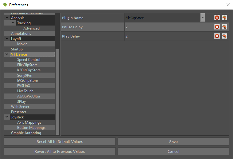
Plugin Name
Select FileClipStore for video clips stored on a local disk.
Pause Delay
Default setting is 2 frames.
Adjust this if you find that when playing the video clip it does not pause at the selected timecode once analysis graphics have been added.
Play Delay
Default setting is 2 frames.
NOTE: Restart Tactic for any changes to take effect.
FileClipStore
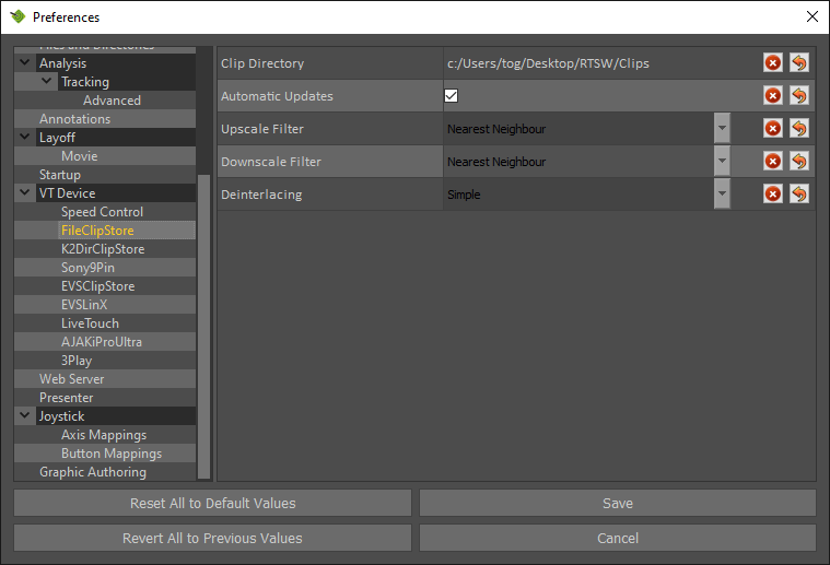
Clip Directory Set this to the file path of the base directory for your clips.
- e.g. DesktopRTSWclips
Automatic Updates
Set this to automatically update the thumbnails in the Clip Browser.
Upscale/Downscale Filter
When using file based clips, these filters determine how video gets scaled if you feed a different video input than expected.
Different filters have different performance effects and have visually different results. Experiment with the scaling filter to find the one that suits your needs best.
Deinterlacing The method used to convert interlaced video clips.
NOTE: Restart Tactic for any changes to take effect.
Using a K2 via FileClipStore
If you have mounted a K2 Summit or Solo onto your machine using DLC/SNFS, You can mount to a point located inside of the Clip Directory specified above. The K2 clips will then appear in the same way as the regular local disks do. Note that the K2 uses a ‘reference’ movie to hold all the various streams related to that clip.
If the K2 is not creating reference movies then the K2 clips will be shown as Directories with the video ‘chunks’ located within. It is recommended that you enable reference clips on the K2 to seamlessly integrate network mounted K2 clips within the FileClipStore system.
If you are recording back to the K2, ensure you have correctly set up the HotBin on the K2 and it is visible within the directory structure defined here. Refer to the GV documentation on HotBin Import.
K2DirClipStore
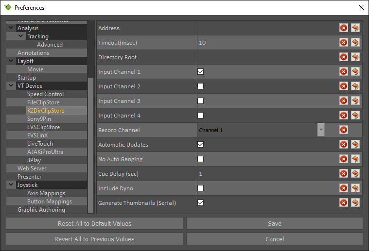
Address
Set to the network address of the control port of the K2. This is a standard IP address or hostname. E.G.: 192.168.10.10, or K2Control.
NOTE: based on the entry address typed here tOG will determine whether to use network or serial connection. Setting the address to tty… or COM… will select serial control. An IP address will select network connection.
Timeout
In case of serial control it indicates the timeout on trying to send a command to the K2 before an error returns on failure.
Directory Root
Type in a file path to limit which directories on the K2 will be searched and made available. For example, default/steve/tmp would only look inside of the “tmp” directory on the K2.
Input Channel 1-4
Tick the boxes next to the channels that Tactic will control on the K2 server. The corresponding channel selector buttons will become available on the VT Control section.
Record Channel
When using the Record functionality, this defines which channel of the device to control for recording clips.
Automatic updates
Turn on automatic update if you want Tactic to automatically update its list in sync with the VT device. Clip changes on the VT device will be reported from a known sentinel point such as a refresh. If you delete or add clips these changes will automatically update Tactic Clip window.
NOTE: network connection is preferred to serial connection because the network is faster and the serial does not support auto thumbnail creation.
Sony9Pin
The Sony9Pin (BVW75) clip plugin provides VT control over any video device that supports this protocol. Tactic has been qualified with major brands such as K2, EVS, Sony Digital Betacam and Doremi.
The EVS is connected by a straight-through pin-to-pin RS422 serial cable to a serial extension panel of the DVS Video Board on the tOG PC.
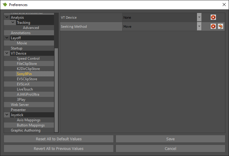
VT Device
This setting defines how the System responds to some of the controls. It especially effects how the eject button works.
Seeking Method
This defines which Sony command is used for clip seek, If you are experiencing problems with seeking on clip restart you may find that changing this setting helps. This is especially true for VT Decks.
Timecode Settings
Navigate (press F10) to tOG Sports Preferences -> Video dialog. Set Timecode to either Serial, or Embedded.
Serial
The timecode will be read from the serial feed.
Embedded
The timecode will be read from the SDI video feed.
EVS configuration
Sony9Pin plugin
This section describes how to set up an EVS Video Server for Sony9Pin control under Tactic. It assumes that the systems have been connected appropriately as described before. The control protocol used is Sony BVW75 (9 Pin) and allows simultaneous control between the EVS and the LSM Remote controller.
Although the EVS configuration is outside the remit of this document a brief outline is provided here to assist operators in setting up and troubleshooting the system. Bear in mind that these settings were correct at time of writing, but if the EVS workflow has changed since then they may not be correct – consult the relevant technical studio/broadcast staff to check. At this time, a single EVS is being used for both the Tactics system and Rostrum System.
There are 3 EVS configurations that need to be setup for correct Tactics/Rostrum operation.
The first is to configure the EVS to have 3 inputs and 3 outputs. This allows the EVS to be controlled by 3 separate devices.
The second is the Remote RS422 control. This is done through the LSM controller.
Multicam Version 10
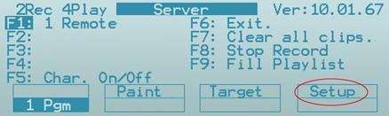
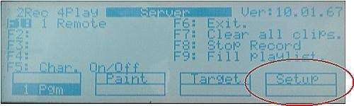
From the Main system menu (Shift+Menu) select Setup (Shift+D). This will change to:
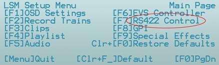
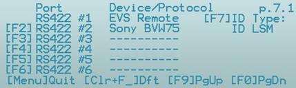
Set the control for input 2 for Sony BVW75. This means that you MUST connect the serial link from the Tactics table into serial i/p 2 on the back of the EVS.
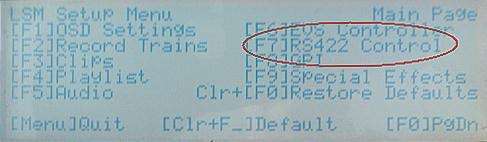
- Now select page 7.2 (F10)
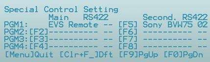
This page dictates which program channel the devices control. Set them up as shown above. This says that the LSM and Sony (Rostrum) can both control PGM1.
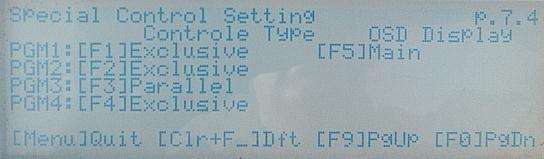
- Now select Page 7.4 (F10 twice)
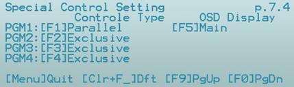
This page determines how the LSM and Sony (Rostrum) are to share control.
- Setting F1 to Parallel means that they can both control the channel together rather than 1st control 2nd control.
Multicam Version 11
LSM Remote Main page
- From the Main system menu (Shift+Menu) select Technical Setup (press F10).
- Then use F10 to advance pages and F9 to go backwards in the Technical Setup menu.
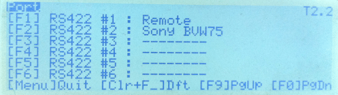
LSM Remote Main System menu
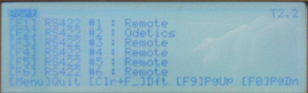
- Find page T2.2 – as indicated in the top right corner of the screen and set by pressing F2
- Then using the Jog Wheel to select SonyBvw75 from a list of available protocols:
- LSM Remote Page T2.2
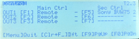
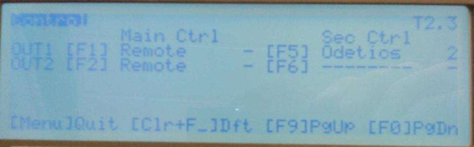
- Advance to page T2.3 and set SonyBvw75 as a secondary controller.
LSM Remote Page T2.3
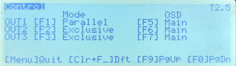
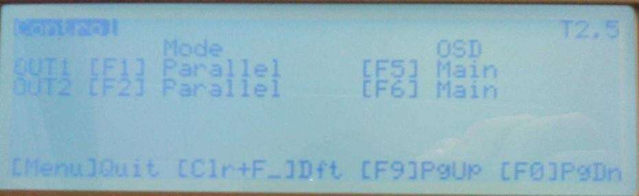
- Go to page T2.5 where you can set SonyBvw75 to parallel or exclusive.
LSM Remote Page T2.5
- When you finished you can press Menu to quit the setup menu and the system will prompt to save the changes you have made. It is necessary in order to use these changes. Press Menu again if you are happy with your changes.
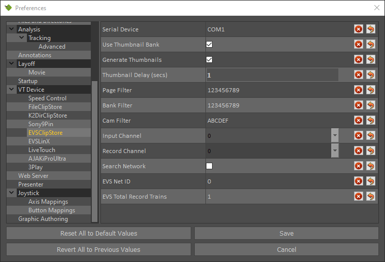
EVSClipStore
This plugin provides control over clips stored on an EVS using the Odetics protocol through serial RS422 connection to a generic serial port on the Tactic machine. Video streams are delivered over SDI.
|
Property |
Description |
|
Serial Device |
Set to the serial port that is connected to the EVS. This is usually COM1. |
|
Use Thumbnail Bank |
This option has two features:
|
|
Thumbnail Delay |
Used in thumbnail creation. Set the delay between EVS starting to load a clip and Tactic grabbing the thumbnail. That is in case it takes too long for the EVS to load a clip. |
|
Page Filter |
Include only these page numbers (0-9) when updating the clip list. |
|
Bank Filter |
Include only these bank numbers (1-9) when updating the clip list. |
|
Cam Filter |
Include only these camera inputs (A-F) when updating the clip list. |
|
Input Channel |
Set the EVS OUT channel to be controlled by the plugin. |
|
Record Channel |
When using the Record functionality, this defines which channel of the device to control for recording clips. |
|
Search Network |
FOR FUTURE USE. |
|
EVS Net ID |
Set the target EVS server Net ID (0-99). Please see the EVS documentation for further explanation on EVS server networks. |
Creating Thumbnails
The EVSClipStore plugin uses the SDI video input signal of Tactic to make thumbnails for the clips in the built clip list. For this it loads each clip on the EVS one after the other on whichever PGM channel Odetics is configured. If Use Thumbnail Bank is selected then only specific clips will load. Read the Use Thumbnail Bank section for more details.
NOTE: make sure that this process will not interrupt your production.
Use Thumbnail Bank
In this mode when the clips are prepared, the operator should clear all clips from other channels and save the clips on Cam A. They should then make a single frame clip from the clip on Cam A, and save it to the corresponding Page and Bank number on Cam B. This clip will be the thumbnail clip and it will only be used to generate the thumbnail.
E.G.: supposing there is a clip with ID 133A/00 the thumbnail MUST exist on 133B/00.
NOTE:
- Make sure that the Cam Filter settings exclude the channels where the thumbnail clips are stored. (Cam B usually)
- It is actually not restricted which channel to use for thumbnails and clips. tOG will always look for a clip with the matching Page and Bank number on the channel consecutive to the selected clip’s channel: A->B, B->C, C->D,…
EVS configuration for the EVSClipStore plugin
Video connection
The EVS server provides VT source material via the SDI input to the Tactic system. The DVS video card is equipped with 3 main BNC connectors. These are labelled InA, OutA and Ref. The selected channel on the EVS should be connected to the InA BNC on the DVS card. The OutA connector provides HD SDI output for Tx. This combines the EVS input with telestration. The Ref input is not used since tOG is synch’d to its SDI input. Section 2 below describes the video setup in tOG.
Serial connection for VT Control
The second connection between the EVS and the Tactic system is the RS422 Serial control feed. The serial connection is a straight thru cable and may be extended via CatV at the Studio panel or via fibre. The port on the EVS should be on the same channel as the EVS video output. At the current time this has been designated channel 3 on Yellow EVS – but this may change!
The Serial cable is terminated at the PC thru an RS422/232 converter to the COM1 port. The converter is vital and correct operation will not occur if it is omitted. Ensure it is connected the correct way round with the 422 end plugged in to the cable going to the EVS and the 232 end plugged into the computer.
The final stage in EVS configuration is the setup of Odetics protocol on the EVS LSM controller.
Exclusive and parallel modes
The Odetics protocol can be used in three different modes on the EVS:
- Odetics being set as a Main Controller on a PGM channel. No other controllers including the LSM can access that channel.
- Odetics being set as a Secondary Controller in Exclusive mode. Both the main (LSM) and secondary (Odetics) controllers receive permanently the status of the channel(s), but only one controller at a time is able to actually control the channel. The main controller can decide at any time to pass the control to, or to retrieve the control from the secondary controller.
- Odetics being set as a Secondary Controller in Parallel mode. Both the main (LSM) and secondary (Odetics) controllers receive permanently the status of the channel(s), and both controllers are able to control the same channel at any time. Either of both controllers can take the control as long as the other controller is not executing a command. The control can thus be freely passed on from one controller to the other.
The following sections describe how to set all this up on Multicam v10 and on Multicam v11.
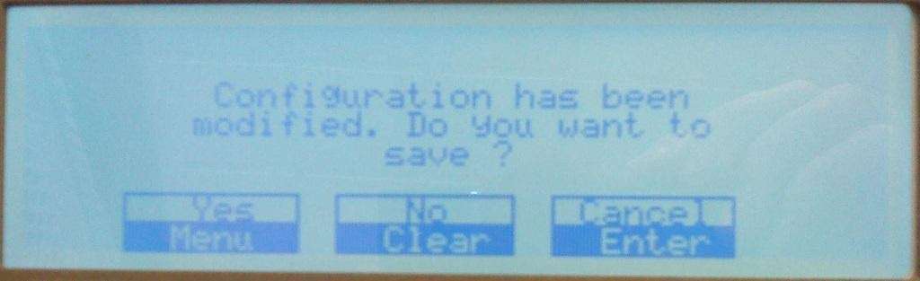
LSM setup on Multicam 10
- The LSM Setup menu is selected by pressing Shift+Menu
- From here select the setup menu Shift+D
- Now select F7 for the RS422 Control screen
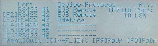
This page (7.1 – tog right) specifies the physical connection channel on the back of the EVS. To change the selection, press the function key corresponding to the desired channel – in this example channel #3. Press F3 to select, spin the LSM jog wheel to the right until it shows Odetics. Now press F3 again to confirm.
- Now select F10 for the next page 7.2.
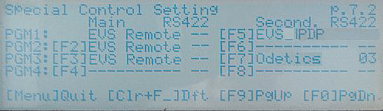
This page selects which program the connected channel controls. It is necessary for Golf that PGM3 (Yellow) is available for both EVS operator and Presenter (but not at the same time). To achieve this we can select parallel operation between LSM and Odetics. To do this, select F7 and spin the LSM Jog wheel until it shows Odetics 03. Then press F7 again. This allows both the LSM and odetics to control PGM3. Note in the figure that the name selected is ‘Odetics 03’. The 03 corresponds to the channel selected on the previous page 7.1.This allows you to differentiate between multiple setups of the same protocol. Press the function key again to confirm.
- Press F10 twice now to get to page 7.4
This is the final page for the 422 setup and allows you to select whether the control you have setup operates exclusively on the selected PGM or in parallel with an LSM controller. In this case we want parallel operation on PGM3. Press F3 and spin the LSM jog wheel to select Parallel, press F3 again to confirm.
NOTE: You will get an EVS warning message telling you your configuration is incomplete – you can ignore this.
LSM setup on Multicam 11
In this version of Multicam the menu structure in the LSM Remote changed slightly. The following is a working example on how to use Odetics with Tog through a RS422 serial connection.
In this example, on all the EVS channels the LSM Remote is set as the main controller and Odetics is set as a secondary controller in parallel mode on channel PGM1. The serial cable is plugged into RS422 #2 connector on the server.
- From the Main system menu (Shift+Menu) select Technical Setup (press F10). Then use F10 to advance pages and F9 to go backwards in the Technical Setup menu.
- Find page T2.2 – as indicated in the top right corner of the screen and set by pressing F2 and then using the Jog Wheel to select Odetics from a list of available protocols:
- Advance to page T2.3 and set Odetics as a secondary controller.
- Go to page T2.5 where you can set Odetics to parallel or exclusive.
- When you finished you can press Menu to quit the setup menu and the system will prompt to save the changes you have made. It is necessary in order to use these changes. Press Menu again if you are happy with your changes.
EVSLinX
Overview
The EVSLinX plugin is used to access and control clips stored on an EVS video server. Using the LinX protocol over network Tactic can control program and recording channels. Video streams are delivered over SDI.
Main features
- Full Tactic VT control on up to 2 PGM channels on the EVS using LinX as a Main Controller.
- Monitor and control any 2 of the Recording trains at once in E2E mode on two separate tOG input channels.
- Full Tactic VT control on any of the selected recording trains.
- Record back to an EVS recording train in real time including Tactic graphics and clip creation.
- Create a clip list with thumbnails in tOG. Thumbnails are transferred from the EVS through Gigabit Ethernet via the Foxx protocol.
- Auto update Tactic’s clip list in response to new clip creation and clip changes made on the EVS.
NOTE: EVS only supports LinX on Windows operating systems.
Connections
In a typical configuration the connections and work-flow between tOG and the EVS server would be as follows:
Network connections
- EVS Pc LAN socket → main Ethernet Network.
- EVS Gigabit Ethernet socket 1 or 2 → main Ethernet Network.
- TOG Pc network socket → main Ethernet Network.
NOTE: For efficient data transfer to grab thumbnails from the EVS, all the Ethernet Network infrastructure must have Jumbo Frames capability. See the Setup Jumbo Frames section.
Video SDI connections
- EVS OUT-2 → tOG IN-1
- EVS OUT-3 → tOG IN-2
- tOG OUT-1 → EVS IN-1
In this configuration tOG can control two separate PGM channels on the EVS, build its own customized clip list from the clips that exist on the EVS server and create thumbnails for them by grabbing any 1 frame of the clips.
After building an analysis sequence in Tactic the clip can be recorded back to the EVS with the overlaid graphics, then Tactic will make a clip on the server at the specified time codes.
Network connections on the Tactic PC
LinX
The LinX protocol controls the EVS channels and connects to the PC LAN socket on the server.
Foxx
Tactic uses an Ethernet network to transfer thumbnails from the EVS by a protocol called Foxx. It uses one of the Gigabit Ethernet sockets on the EVS server. The whole network infrastructure and the used network port on the Tactic PC need to support Jumbo Frames for fast transfer speed. Foxx can work without Jumbo Frames but the transfer gets considerably slower.
NOTE: Jumbo Frames is not necessary for LinX.
Local IP setting
If there are more than one physical, active network connection on the Tactic PC on the same subnet to the EVS network (for example, if you are using separate connections for LinX and FoxX) then it is possible that LinX cannot reliably detect which local connection to use. In this situation you can set the Local IP address in the Preferences menu to avoid this. This is the IP address assigned to the network port that connects to the EVS. Check the Windows network settings.
It is recommended, however, that you either use a single Jumbo Frame network connection or use 2 different subnets for the 2 connections.
Setup Jumbo Frames
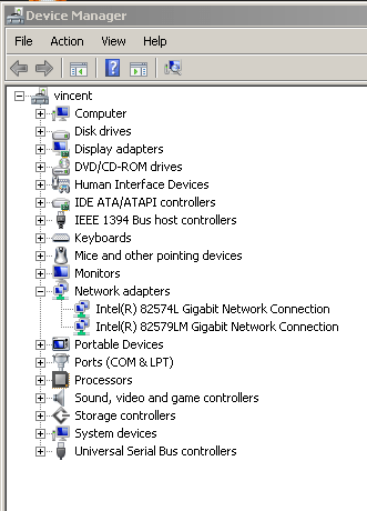
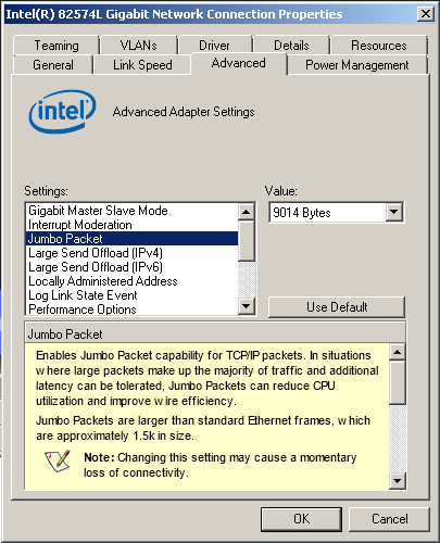
Method is based on a HP z820 PC:
- In Windows: open Device manager
- Double click on the used Network adapter
- Select the Advanced tab from the pop-up window
- Find Jumbo Packet in the list
- Set the largest value (9014 Bytes)
The Device Manager and the Network adapter’s pop-up window in Windows 7 below:
EVS configuration for LinX
This section will explain how to set up a working configuration for LinX by using the EVS Multicam 11.01.74 software interface. See the EVS documentation for further details.
- Open up the main configuration window.
This is the main window that appears after the EVS started up. If the Multicam is at the clip list view then you must exit by either pressing ALT+Q or by using the LSM Remote.
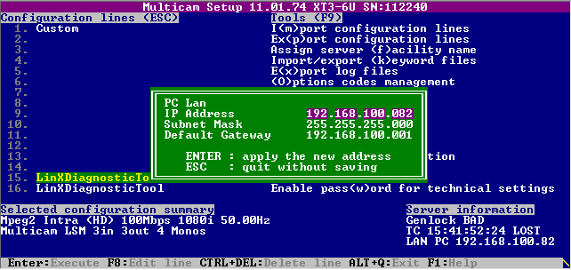
Network connections
To set the PC LAN port IP address:
- Select a configuration line at the left side of the setup window
- Press L
- Set the IP address, Subnet and Default gateway
- Press ENTER to apply
Main configuration window on EVS from Multicam 11.01.74, see below:
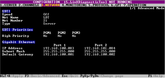
To set the Gigabit Ethernet configuration:
- Select a configuration line under the setup window
- Press F8 then F3 for Advanced Mode
- Navigate to the NETWORK window by pressing the RIGHT arrow on the keyboard
- Press TAB several times to navigate to the IP settings
- When finished press ALT+A to apply
NETWORK configuration window on EVS from Multicam 11.01.74, see below:
Setting up channels for LinX
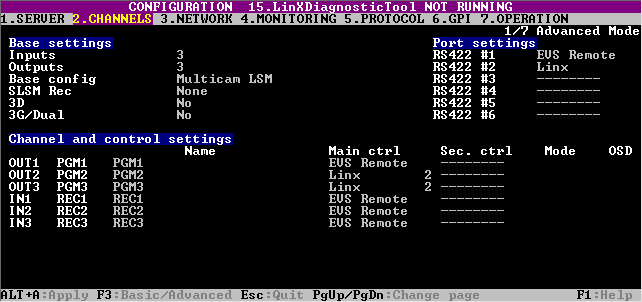
To set the channel configuration on the EVS:
- Select a configuration line under the setup window
- Press F8 then F3 for Advanced Mode
- Navigate to the CHANNEL window by pressing the RIGHT arrow
- Press TAB several times to navigate to the required line
- Set Base config to Multicam LSM.
- Set one of the RS422 ports to LinX.(This port will be used exclusively by LinX)
- Set LinX as a Main controller on one or two OUT channels depending on how many channels tOG will need to control.
NOTE: in Multicam LSM mode PGM1 and RS422 #1 have to be set to EVS Remote.
- When finished press ALT+A to apply
CHANNELS configuration window on EVS from Multicam 11.01.74, see below:
Setup Tactic for LinX
To open the EVSLinX plugin navigate to the Clip tab at the bottom left corner of the Tactic operator’s interface and select EVSLinX in the “Clip Control Plugin” drop-down menu.
Opening EVSLinX plugin for the first time
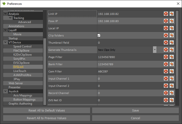
On selection of the EVSLinX plugin for the first time after installing Tactic the plugin will not be initialized correctly. The first item to set is the LinX IP address of the EVS server. See the EVS Configuration for LinX section to determine this address.
Once the LinX IP is set LinX will try to re-initialize and if successful Windows will prompt to allow network connection to the EVS server. This will have to be authorized through a Windows pop-up dialogue.
Until LinX is configured correctly Tactic will repeatedly attempt to open the communication channels used to communicate with the EVS. This will result in various error messages appearing on the Tactic debug window until successful connection . See LinX debug output for further details.
|
Property |
Description |
|
LinX IP |
PC LAN connection IP address set on the EVS server for LinX |
|
Foxx IP |
Gigabit Ethernet IP address set on the EVS for Foxx thumbnail transfer |
|
Local IP |
This has to be set if there are more than one active network ports on the tOG PC. Set this to the IP address of the network port that is connected to the same network as the PC LAN port on the EVS. |
|
Clip folders |
Thumbnails will be organized into directories according to the assigned KEYWORDS in the clip. See the Custom Clips section for more details. |
|
Thumbnail field |
The field number in the EVS clip from which thumbnails will be created. |
|
Page Filter |
Include only these page numbers (0-9) when updating the clip list. |
|
Bank Filter |
Include only these bank numbers (1-9) when updating the clip list. |
|
Cam Filter |
Include only these camera inputs (A-F) when updating the clip list. |
|
Input Channel 1 |
Set EVS OUT channel (1-6) that is connected to tOG video IN 1. |
|
Input Channel 2 |
Set EVS OUT channel (1-6) that is connected to tOG video IN 2. |
|
Recording channel |
Set EVS recording train (1-6) from which the clips will be created. |
|
EVS Net ID |
Set the target EVS server Net ID (0-99) if there is more than one server accessed from the “local server”. Please see the EVS documentation for further explanation on EVS server networks. |
|
Automatic Updates |
Default to false. Automatically update tOG clip list with changes made on the EVS regarding add/remove/rename clips. |
|
Show OSD |
Outputs text information on Linx channels the same way the Main channel does. Clip name, Timecode, etc.. |
Using the EVSLinX plugin
Build clip list
Clip list is always built and updated based on the Page, Bank, Cam filter settings and the Clip Folders option in the Clip tab.
- Press F6 to open the Clip Store window.
- Click on Refresh cliplist
- Click Yes All to the “Generate Thumbnails?” dialogue.
The thumbnails will be copied into the Tactic directory at:
- C:Users…DesktopRTSWTacticProThumbnails
Thumbnails are named accordingly to the clip Lsm ID. For example:
- 111A_00.png
REPLACE BITMAP BELOW
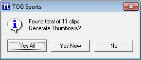
When the Thumbnail dialogue appears there are three options:
- Yes All: make a thumbnail for every clip in the built clip list.
- Yes New: going through the clip list for each clip tOG looks for a matching thumbnail file of the correct format in the Thumbnails directory. For every file that is missing, tOG will grab a thumbnail.
- No: no thumbnails will be transferred. tOG will still look for existing thumbnails in the Thumbnails folder and use them or set a default blank thumbnail for the clip.
Loading clips from clip list
To load a clip find the corresponding thumbnail in the clip list and drag it onto the analysis window.
VT control with EVSLinX
The Tactic VT control under the EVSLinX plugin works almost the same as under all the other clip control plugins except for little differences that will be detailed below.
Channel selector
In the second row of the VT Control panel the previously set controlling channels can be switched in-between. The number indicates to which video input channel on Tactic is the EVS LinX channel connected.
This can be set in the plugin parameter list at Input Channel 1 and Input Channel 2.
REPLACE BITMAP

The time code display always displays the selected channel’s time code. The greyed out channel selector buttons indicate that those channels are currently not available on your Tactic system. This can be because of a preferences setting or because of your current system or Tactic version’s capabilities. To check this setting:
- Open Preferences -> Video tab -> Input -> Number of channels.
NOTE: the EVSLinX plugin supports control over only 2 channels of the EVS at once.
Gang mode
The G button switches VT Control into Gang mode. In this mode the time code display always follows Input Channel 1. The Rewind, Play, Fwd, Pause, Jog, Shuttle and SlowMotion controls affect all the channels that are lit green as long as they have an EVS clip or train (LIVE) loaded. When any of the clips reach their TC OUT or TC IN they stop but the rest of the channels go on.
REPLACE BITMAP

Eject
The Eject button takes the selected channel into a recording train’s live time code (a.k.a E2E mode). Ganging and all the VT Controls work normally. After using VT control, to go back to the live time code hit Eject again.
NOTE: in LIVE mode LinX plays 2 seconds late to the real time recording.
To choose the recording train to be controlled by the selected VT Control channel in LIVE mode, click on EJECT repeatedly which will cycle through all the available recording trains.
NOTE: LinX does NOT need and cannot to be set as a controller on any REC channels on the EVS in order to inject into LIVE (E2E) mode. The REC channel on the EVS will work seamlessly and regardless of LinX’s presence.
Recording clips on the EVS
The purpose of this feature is to be able to record the output of Tactic onto an EVS recording channel and create a clip in chosen time-codes. To achieve this, the user has to make sure that the EVS is continuously recording the Tactic output at the time when the Tactic analysis sequence starts.
The clip starts when the operator presses Replay and ends when the operator dis-engages the Record button or a MarkOut position is hit in the stack. These two points will be the TC IN and TC OUT points of the clip that is created on the EVS. These mean SHORT TC points, therefore regardless of the guard-bands.
NOTE: make sure that the EVS is currently recording the tOG output because tOG will not check this when creating clips.
Create a clip from Tactic
Get ready to record:
- Eject to E2E or
- Build a clip list with EVSLinX plugin opened and
- Load a clip from the clip list.
- Make a graphic stack on the current video
- Make sure the EVS is actually recording the Tactic output.
Replay and create clip:
- Press Record in Tactic.
- Press Restart
- In the pop up window put an available Lsm ID in this form: 111A. Make sure its upper case. Then set the name of the clip and click on OK.
- Press Replay, which will also set your TC IN for the clip – that’s the current time of the day on the EVS clock
- Anything from now on will be part of the clip in real time until you press (disengage) the Record button which will also set the TC OUT of the clip on the EVS. Then the clip appears on MultiCam and on the tOG clip list too as long as the clip filters are set to include the LSM ID chosen for this clip and AutoUpdate is set true.
The Record button can be disengaged automatically on a precise TC through the stack by using the Mark Out item. When the stack hits Mark Out the record will finish at that point in time (+ some latency of the data transfer to EVS) automatically.
When pressing Restart the clip will jump back to the first stack item’s On TC – minus the pre-roll setting in the Vtr delays editor under the VTR tab.
To set a TC IN automatically for the clip start the stack with a Mark In item and set the pre-roll to 0. In this way the TC IN will be made when the stack hits the On TC of Mark In.
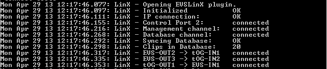
EVSLinX debug output
Successfully initialized LinX with 2 PGM channels and one recording channel. LinX is configured to control through RS422 port-2 on the EVS.
Channel connection error
“LinX – A player channel must be set to load clips. Set Input Channel 1 or 2 to the configured LinX port.”
– No channels are set on both Input channel 1 and 2.
“LinX – connecting EVS-OUT1 -> tOG-IN1 failed.”
“LinX – connecting EVS-OUT4 -> tOG-IN2 failed. Error: Error during open access”
– Channels settings are incorrect. Failed to connect EVS PGM1 and PGM4 to tOG. Check EVS configuration whether LinX is set to control these channels or change Input channel 1 and 2 to different EVS channels.
Time code error
“LinX – Failed to get time code Error: Bad channel type”
1) Didn’t set Input channel 1 and 2.
2) Only either Input channel 1 OR 2 is set correctly but the VT Control channel selector is on the wrong channel.
Lost network connection
“LinX – Failed to get timecode Error: A time-out occurred”
“LinX – Lost IP connection. Error: Connect error. Trying to re-open EVSLinX plugin.”
“LinX – IP connection failed. Error: A time-out occurred”
– All these messages suggest that you have lost the network connection to the EVS. If the error message keeps appearing in a constant rate it means your connection is permanently off.
Every time the connection is lost Tactic will try to re-initialize the plugin.
“LinX – Database connection failed.”
“LinX – Syncing Database failed.”
– When the database connection or synchronization fails but the IP connection is fine it means the database management was busy at the time and Tactic will try to re-open the connections.
EVS – Common plugin features
Keywords in Tactic
REVIEW BELOW
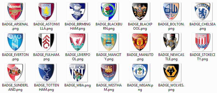
The Clip information system in Tactic relies on the clips being arranged in a particular fashion on the EVS. It reads the Clip ID, Clip Name and Keyword 1 and 2. Clip ID is internal and assume LSM ID format. The Clip name is used to annotate the clip in the clip list scroll window. The Keywords 1 and 2 are used to determine the Home and Away teams respectively.
The order of matches are determined by the order of the clips on the EVS. So if the first clip is MANUTD vs CHELSEA this will appear first in the list. It is therefore vital that the Keyword on the EVS matches the Badge names in the Tactic System. Case is important, i.e. ARSENAL not Arsenal.
The default badges in tOG Sports are to be found in this folder:
- C:Users…Desktoptog-4.5_r14497tOG Sports3DGMDatatOG SportsBadges
To match Keywords with these badges the Keywords have to match the team name as shown in the badge file names. For e.g.:
- File name: BADGE_ARSENAL.png
- Keyword: ARSENAL
The default badges therefore will be matched with the following Keywords:
|
ARSENAL |
ASTONVILLA |
BIRMINGHAM |
BLACKBURN |
BLACKPOOL |
BOLTON |
CHELSEA |
|
EVERTON |
FULHAM |
LIVERPOOL |
MANCITY |
MANUTD |
NEWCASTLE |
STOKECITY |
|
SUNDERLAND |
TOTTENHAM |
WBA |
WESTHAM |
WIGAN |
WOLVES |
Default badges in Tactic, see below:
Custom Clips
REVIEW BELOW
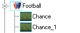
You can sort clips into custom folders instead of sorting in a match specific order as seen previously – into a folder named “ROONEY GOALS”, for e.g. In order to do this you will have to make the following steps:
- Set Keyword 1 for a clip to “ROONEY GOALS” and leave Keyword 2 blank. You will have to edit the Keyword file on the EVS to do this.
When you refresh the clip list on the tOG Sports System, a directory (folder) will be created with the name “ROONEY GOALS” but no icon will be found. There are two ways to assign an icon to this custom directory:
- Drop a custom icon onto the tOG Sports system as detailed in the Editing Directory Icons section.
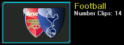
- Put an icon into the “tOG Sports3DGMDatatOG SportsBadges” folder on your PC and name it the same as the keyword you have chosen + the “.png“ extension.
E.G.: if you set Keyword 1 as “ROONEY GOALS” the icon will have to be named as: ROONEY GOALS.png
EVSClipStore vs EVSLinX
This table collects the main technical differences between EVSClipStore and EVSLinX plugins. This is to help decide which plugin may work better for a particular production.
|
EVSClipStore |
EVSLinX |
|
|
Connections |
||
|
Tactic control over EVS |
Serial cable + rs422 converter or USB-Rs422 |
LAN via main Ethernet network |
|
Tactic video I/O |
SDI via video I/O boards |
SDI via video I/O boards |
|
Clip thumbnail transfer to Tactic |
Via SDI |
via network by Foxx protocol |
|
EVS setup |
||
|
EVS channel occupation |
Can be set as secondary controller on any EVS player channels, working in parallel with an LSM control. |
Needs to occupy a whole EVS channel, taking exclusive control over it. (This is under review by EVS) |
|
Compatibility |
Requires Odetics protocol being available on the server. It’s an old protocol so very much available and compatible to old servers and Multicam too. |
– Requires Multicam 11.47 + – Requires network Multicasting capabilities for Clip List Auto Update – Jumbo Frames compatibility on the entire network infrastructure is desirable for Foxx thumbnails |
|
tOG Features |
||
|
Making clips from Tactic output onto EVS (record+clip) |
Only manually via LSM |
Via Tactic interface with precise TC |
|
Clip List Auto Update |
No support |
Tactic Clip List is managed by a regularly synced database. Any changes made on the EVS will appear in tOG too. |
|
Clip List thumbnails |
Requires exclusive control over one EVS channel, temporarily. For every thumbnail: – Tactic loads a clip on EVS – records the first frame onto disk via SDI input – scales the picture to thumbnail size – Takes 1-1.5 sec each |
All in the background and also occurs for each Auto Update. – Tactic starts an app that’s utilising Foxx. – Grabs a full size video frame from required clip via network – Scales the picture to thumbnail size – Takes 0.3-0.8 sec each |
|
Channel ganging |
No support |
2 channels can be controlled simultaneously via frame accurate ganging |
|
E2E – Eject (controlling LIVE recording trains) |
Repeated eject-clicks cycle Tactic through the channels. No indication of which channel is controlled. |
Repeated eject-clicks cycle tOG through the channels. Current channel is indicated under Clip List at “Clip Name”. |
|
EVSClipStore |
EVSLinX |
K2 DLC
System Overview
This guide is to provide a systems operators, support staff and engineers in the setup, configuration and operation of the K2 Video Server using DLC (Distributed Lan Client) to provide clip information for Tactic direct from a K2 Summit/Solo or San system. The connection between the Tactic system and K2 is network based and utilises a DLC client/server mechanism called Storenext by Quantum. The diagram below illustrates the system architecture.
K2 DLC System Architecture, see below:
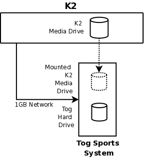
The principle behind the connection is basic file sharing. The media drive on the K2 is shared and is mounted onto the tog system. The DLC client provides a file system called CVFS or SNFS to allow this to be done.
Requirements and Warnings
There are a number of requirements to allow network mounted clip playback using SNFS/DLC. These are
- SNFS/DLC with the K2 is not guaranteed to be real time in all situations. There is a finite amount of bandwidth available on the K2 and if this is being shared with SAN backup, DynoPA, Proxy control then your playback may not be in realtime. You can still play and record back to the DLC and the completed clips will be real time. But if you are trying to play direct to air you should fully test your K2/Tog setup beforehand.
- Ensure you have JumboFrame support enabled on your network NIC’s If you do not you will not get the optimum performance and you will increase the chance of dropping frames.
- Ensure you have Reference clips enabled on the K2. Otherwise, all clips without reference mov files will appear as directories in Tactic.
- Ensure you are using the correct version of the SNFS Client for the K2 you are connecting to. RTSoftware does not supply the SNFS Client for this feature. If you require this then you should contact either GrassValley or Quantum.
Connection
The connection between the K2 and the Tactic system relies on a 1Gb network link. The network connections assume that network access is configured on both systems. It will also depend on whether you are running a DHCP server or not. If you are not running DHCP you will have to manually assign an IP address to the Tactic system.
The network cable should be connected to the Tactic system using the lower of the 2 network ports on the back of the machine (usually labelled ASF). You should have been supplied with a DLC.zip file that contains installers for both Windows and Linux. It also contains this document as well as other docs for Windows configuration.
Linux
REVIEW BELOW
You can access network setting on a Linux system by clicking on the RedHat menu (bottom left on the task bar) and selecting System->Administration->Network.
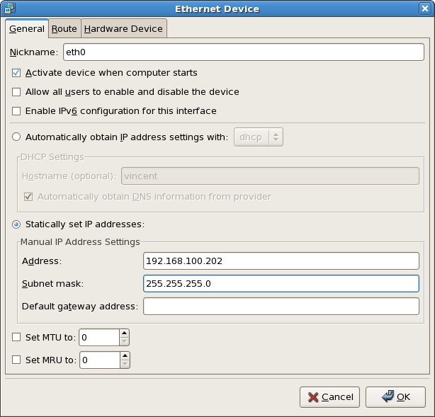
If you are running a static IP network:
- Select the active network from the list (usually eth0)
- Select Edit.
- Check that there is an entry in the DHCP Setting section for a Hostname
- If there is not one there then delete Automatically obtain IP Address and enter on.
- Now select Statically set IP Address and fill in the IP Address you have been assigned on the K2 network along with the Subnet address. (You do not need a default gateway unless you are given one).
If you are running DHCP select this option and ensure there is a Hostname entered:
- Log in as root and type gedit /etc/hosts
You should now edit the hosts file. To do this:
- Open a terminal window
- Enter into here the Tactic hostname with its IP address if it is static
- Enter the hostname and IP address of the K2 if this is static.
Configuration
The configuration of DLC connection relies on a DLC Server running on the K2 system and a DLC Client running on the Tactic system. This document does not cover the installation of the DLC on the K2 system. Please refer to the K2 DynoPA System manual for information on how to set this up.
Linux Installation and Configuration
REVIEW BELOW:
To install under linux locate the DLC package. This consists of an rpm. The version at the time of writing is:
snfs-client-RedHat50AS_2618-3.5.1.10866.x86_64.rpm
This is located in the DLC.zip under the Linux directory that you should have been provided with. To install this open a command shell Terminal. To do this:
- Click on the RedHat main menu on the taskbar bottom right and goto Accessories->Terminal.
- This will pop up a window with a command prompt. Login as root by typing ‘su’ followed by the root password (usually ‘tog’).
- Navigate to where the package is and type in:
- rpm -Uvh snfs-client-RedHat50AS_2618-3.5.1.10866.x86_64.rpm
This will install the package.
- Alternatively, double click on the package and install using the package manager.
Once the package is installed you will need to do the following:
Setting up SNFS Nameserver
- Open a command shell and log in as root as detailed above.
- Navigate to: /usr/cvfs/config
- You now need to copy a template fsnameserver file and edit it to point at the K2. Type the following
- cp ../examples/fsnameservers.example fsnameservers
- Now edit the fsnameservers file using: gedit fsnameservers
- Now scroll to the bottom of the file and locate the line starting with# Primary FS Name Server is rock
- Replace the line below with either the name of your K2 server or its IP address:
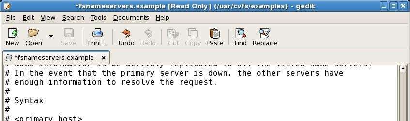
If you are running in a static network you must enter the K2 host name and ensure that you have also entered this into both the K2’s and Tactic hosts file. If you are running DHCP you can enter either – but a hostname is recommended.
Creating the mount point
You now need to create a mount point where the K2 media drive will be mounted to. You can put this anywhere but the convention is in /media.
- Open a command shell and logging as root.
- Type the following: mkdir /media/k2
Enabling mount
To automatically mount the drive you need to put an entry into the Linux mount file. This also gives information regarding the mount parameters. To do this:
- Open a terminal window
- Login as root and type the following: gedit /etc/fstab
- This will open the fstab file.
- Type in the following entry at the bottom of the file:
gvfs_<name of your K2 media drive> /media/k2 cvfs rw,diskproxy=client,threads=32,atimedelay=yes,cachebufsize=512k,auto_dma_read_len th=512k,a uto_dma_write_length=512k 0 0
NOTE: these are ALL ONE LINE
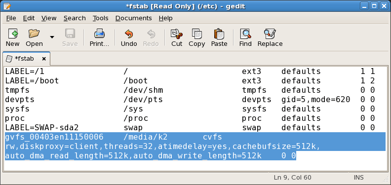
The first piece of text should be replaced with the name of your K2 media drive. These normally always start with gvfs_. In the example below the entry required has been highlighted in blue. The K2 Media volume is ‘gvfs_00403en11150006’.
The second parameter is the mount point you created in 2) above
- Save this file.
You have now completed the installation of the DLC client. Read on to test.
Testing the configuration
To test the connection:
- open a terminal window, login as root and type: mount /media/k2
The system should respond with the following:
Unmounting SNFS filesystems Stopping SNFS Daemons Stopping SNFS PortMapper Waiting for FSMs to finish Waiting for FSMPM to finish
SNFS Stop [ OK ]
Initializing StorNext Filesystem (SNFS) Loading SNFS modules net.core.rmem_max = 1048576 Starting /usr/cvfs/bin/fsmpm. net.core.rmem_max = 131071
Starting /usr/cvfs/bin/cvfsd… Mounting SNFS filesystems
/dev/cvfsctl1_gvfs_00403en11150006 on /media/k2 type cvfs (rw,diskproxy=client,threads=32,atimedelay=yes,cachebufsize=512k,auto_dma_read_length=512k
,auto_dma_write_length=512k,sparse=yes) SNFS Initialized
You should now be able to ‘see’ the clips on the K2 media drive. Confirm this by typing:
ls -l /media/k2
You should get:
- drwx—rwx 2 60001 60001 2048 Aug 31 2011 export
- drwxrwxrwx 19 root root 2048 Mar 30 18:38 media
- drwx—— 3 60001 60001 2048 Aug 23 2011 $RECYCLE.BIN
- drwx—rwx 3 60001 60001 2048 Apr 22 2011 RECYCLER
Windows Installation and Configuration
This guide does not cover the installation of the DLC client for Windows systems. This is extensively covered in the DynoPA system guide – PA_v2.0_ConfigMan.pdf
You will find this in the DLC.zip you should have obtained. The docs and installers are located in the Windows directory of the zip file.
Troubleshooting the K2 DLC
If you cannot successfully connect to the K2 you should check that the K2 is configured correctly. Check the following
- Ensure you have entered the correct information into the Tactic system configurations files
- Ping the K2 Open a Dos or Linux shell and type:
- ping <hostname of IP address>
The K2 should respond:
- 64 bytes from k2control.rtsw.co.uk (192.168.100.81): icmp_seq=1 ttl=128 time=0.090 ms
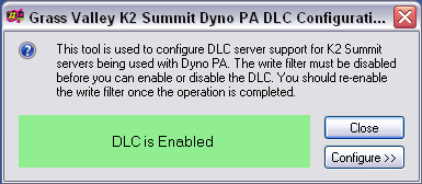
- Is DLC enabled and running on the K2? On the K2 desktop, goto System->All Programs->GrassValley->DLC Config->Launch DLC Tool.
If this is not there then DLC has not been installed. If it is, run it and check that DLC is running. If DLC is not running consult GV docs on how to start.
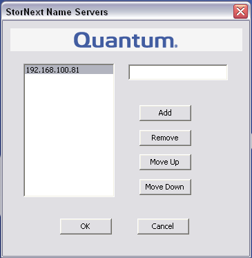
Is the correct nameserver IP address entered?
Run AllPrograms->StoreNext FileSystem->NameServers.
The IP Address of The K2 should be configured. If it is wrong, delete the entry and type in the correct one.
Note: You will need to disable the Write Filter to make permanent changes thru reboots. Check K2 docs for more info.
Is the Name binding correct?
- Open up the Network Setting dialogue.
- Open up Network connections on the K2. Select ‘Advanced Settings’ from the Advanced menu at the top of the dialogue.
- Ensure that the ‘Control Team’ is at the top of the binding list and that ‘Loopback Adapter’ is at the bottom. Use the arrow keys at the side to change.
Clip Browsing
Via Clip Plugins, Tactic provides the ability to browse through clips on a video server device, and to command the device to load those clips for further operation.
For this the Clip List has to be populated. Furthermore the list can be customized and edited in many ways that will be explained in this section.
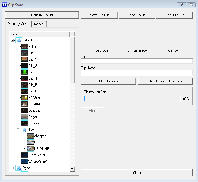
- To start, press F6 to bring up the Clip Store dialog while the main Tactic interface is in view:
Clip Store showing clips on a K2, see below:
Querying Clips
The clip list will be empty by default. To query the clips on the device: Click Refresh Clip List and wait for the operation to complete.
NOTE: Serial based protocols will take much longer to complete than network protocols, as thumbnails must be grabbed by putting the clip to output on the device, and then screen grabbing it. It is recommended to keep the number of clips on the device small (<20) when using serial based protocols.
Editing the clip list
Once you have grabbed the clip list, you can use the Clip Store dialog to edit clip names, directory icons and clip icons.
The Directory View gives you a list of all directories and clips available on the device. By clicking on a directory or clip, the details for that clip will appear on the right-hand side of the dialog.
Editing Directory Icons
REVIEW BELOW:
- Click on the directory that you wish to edit.

- To clear an existing icon, simply click on the icon button you wish to delete.
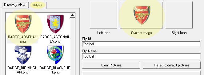
- To drop a new image onto the icon, drag it from the images tab on the left, onto the icon space you want to drop it on.
- Edit an icon in Clip Store
- Click Clear Pictures to clear out all icons for this directory.
- Click on Reset to Default Pictures to reset the icons for this directory to the original ones.
Directory Icons
The directory icon is constructed from 3 separate icons. You may specify as many or as few of these as you want.
Icon editor

Clip Store view
Clip List view
The left and right icons appears offset to the left and right side of the button, in front of the custom image. The custom image sits centrally on the button.
Editing Clip Icons
Clip icons work similarly to directory icons:
- Select a clip in the Clip Store clip browser
- Drop an icon from the image browser onto the Custom image box.
NOTE: in this case you may only edit the custom image – the left and right icons are not available.
Editing Clip Names
- Select the clip that you wish to edit from the Directory View
- On the right hand side, click on the Clip Name, and type in a new name.
NOTE: You cannot edit Directory names, or Clip Id-s.
Saving and Loading Clip Lists
You can save your customisations to disk. When you do this, the last customisation saved will be loaded the next time you start Tactic.In this way, you can pre-prepare a clip list with the customisations you require.
- Click the Save Clip List button to save your clip list
Click the Load Clip List button to load an existing clip list.
