Swift Studio – AR/VR System Administration

AR/VR System Administration
| About | Description |
| Revision | 4.6.5-1.0 |
| History | |
| Authors | Jerry Clark |
Overview
About this manual
The Swift Studio AR/VR System Administration manual is the studio engineers’ reference manual for setting up Swift Studio to operate with the MoSys StarTracker camera tracking system.
About Swift Studio
Swift Studio provides all of the tools required to create all AR/VR graphics and to render, key and composite those graphics over a clean video feed from the tracked studio camera with the Swift virtual camera linked to that studio camera via data received from the StarTracker camera tracking system..
All Swift graphics sit inside a project. A project contains all of the assets required by the graphics that are in it – Examples of assets are fonts, geometries and images.
For details on graphics creation please refer to the Swift CG+ user manual.
Swift Studio is normally started by double-clicking the icon on the Desktop.
About StarTracker
StarTracker is a camera tracking system developed by Mo-Sys Engineering Ltd.
Primarily used to track a studio camera it utilises a large number of calibrated targets (or stars) mounted on the studio ceiling. A small upwards looking camera (or sensor) is mounted on the studio camera and the studio camera lens is fitted with encoders on the lens zoom and focus rings. Images from the sensor (image of the calibrated star field in the studio ceiling), and the lens encoder readings are fed into a central processing unit. The camera position, orientation, field-of-view and other parameters are calculated and packaged up into a data packet that is then sent over ethernet to a pre-set ip address and port number.
About StarTracker Setup and Configuration
This manual assumes that the StarTracker has been fully setup and configured and is mounted ready-to-go on a studio camera.
Mo-Sys Engineering produce an excellent set if training videos that cover StarTracker setup and calibration, starting from a bare studio and an unboxed StarTracker system and ending with a fully calibrated set of targets (stars) in the studio ceiling and with StarTracker deployed to track a studio camera.
The StarTracker training videos are available here:
https://vimeo.com/showcase/8529819
Password: St@rTr4cker
The above videos should be used in conjunction with the StarTracker manual (in particular the Auto-Aligner procedure that has been updated since the video was produced) to setup and configure the StarTracker tracking system.
About Lens Calibration
This manual assumes that the studio camera lens has already been calibrated by RT Software and the relevant lens calibration file (a .zfc file) is available.
Lens calibration is vital for successful VR/AR use. The studio camera lens is fitted with encoders on the zoom and focus rings, and lens calibration enables the field-of-view of the lens to be calculated from the encoder readings.
Mo-Sys Engineering also offers a lens calibration service. Currently Swift Studio only supports the RT Software calibration files.
System Video and Data Connections
Description
Swift Studio runs on a standard but high-powered PC. The PC is fitted with an AJA video card and high-end nVidia GPU.
The PC will also have 2 Ethernet ports, one of which will be connected directly to the StarTracker to receive camera tracking data.
Diagram showing connectivity when using the internal Swift Keyer
Video Connections
The number of video inputs and outputs is dependent on system requirements.
Video Outputs
The number of video outputs depends on how you are using Swift Studio:
Rendering Using Internal Keyer
Swift Studio will be configured to output 1 video channel. This will be assigned to BNC spigot 1 of the AJA card (need at least an AJA Kona-1).
| Spigot No. | Description |
| 1 | Video output (on Kona-1 only this will be on spigot 2) |
Rendering Using External Keyer
Swift Studio will be configured to output 2 video channels. These will be assigned to BNC spigots 1 & 2 of the AJA card (need at least an AJA Kona-4 or Corvid-44).
| Spigot No. | Description |
| 1 | Video output fill |
| 2 | Video output key |
Rendering Using Unreal and External Keyer
Swift Studio will be configured to output 4 video channels. These will be assigned to BNC spigots 1, 2, 3 & 4 of the AJA card (need at least an AJA Kona-4 or Corvid-44).
| Spigot No. | Description |
| 1 | Video output Unreal fill |
| 2 | Video output Unreal Key (garbage matte) |
| 3 | Video output Swift fill |
| 4 | Video output Swift key |
Video Inputs
.Swift Studio supports a maximum of 3 video inputs and the BNC spigots are assigned immediately following the video outputs. The number of video inputs actually required depends on how you are using Swift Studio:
Rendering Using Internal Keyer
Swift Studio requires at least one video input – the clean video from the studio camera.
Other inputs could be used for a virtual monitor and/or video wall:
| Spigot No. | Description |
| 1 | Video output – keyed/composited over camera input (Kona-1 uses spigot 2) |
| 2 | Video input – clean camera (Kona-1 uses spigot 1) |
| 3 | Video input for virtual monitor/video wall (requires Kona-4/Corvid-44/Corvid-88) |
| 4 | Video input for virtual monitor/video wall (requires Kona-4/Corvid-44/Corvid-88) |
Rendering Using External Keyer
Swift Studio does not require a clean feed from the camera but may require other inputs for virtual monitors/video walls.
| Spigot No. | Description |
| 1 | Video output – fill |
| 2 | Video output – key |
| 3 | Video input for virtual monitor/video wall (requires Kona-4/Corvid-44/Corvid-88) |
| 4 | Video input for virtual monitor/video wall (requires Kona-4/Corvid-44/Corvid-88) |
| 5 | Video input for virtual monitor/video wall (requires Corvid-88) |
Rendering Using Unreal and External Keyer
Swift Studio does not require a clean feed from the camera but may require other inputs for virtual monitors/video walls.
The video card BNC spigots will be used as:
| Spigot No. | Description |
| 1 | Video output – Unreal fill |
| 2 | Video output – Unreal key (garbage matte) |
| 3 | Video output – Swift fill |
| 4 | Video output – Swift key |
| 5 | Video input for virtual monitor/video wall (requires Corvid-88) |
| 6 | Video input for virtual monitor/video wall (requires Corvid-88) |
| 7 | Video input for virtual monitor/video wall (requires Corvid-88) |
Reference Sync (genlock)
The PC and the StarTracker processing unit must be referenced (genlocked) to the same source as the camera. The AJA cards and the StartTracker accept traditional 625/525 “black-and-burst” or an analogue HD trisync reference.
The Kona-1, Corvid-44 and Corvid-88 have a reference input spigot. The Kona-4 has a breakout cable that has a genlock input connector.
Data Connections
Swift Studio needs to receive tracking data from StarTracker over ethernet and one of the PC ethernet ports should be reserved for tracking data only. It should be connected directly to the StarTracker using Cat5e or better ethernet cable.
StarTracker IP Configuration
The StarTracker port is configured using the StarTracker monitor and wireless keyboard.
From the “My IP tab” in the Data menu the IPaddress is set from the “Static IP:” select box and the Netmask is set similarly. They should be set as shown below:
PC Ethernet IP Configuration
The PC port is configured using the standard Windows networking tools. It should be assigned a static IP address of 10.10.10.10 with a netmask of 255.255.255.0
StarTracker Configuration for Swift Studio
Once the PC and StarTracker have an ethernet connection and the ports have been configured VNC Viewer can be used to remote-login from the PC to the StarTracker and there is no need to use the Wireless keyboard for further configuration.
StarTracker can send data to 3 devices simultaneously but it is more usual to only send data to one device.
Data Destination IP address and Port
StarTracker needs to be set to send the Tracking data to a particular IP address and port number. Swift Studio must be set to read data from the same port number:
In the above example I have set StarTracker to send data to IP address 10.10.10.10 on port 8010.
Other Settings (turned off)
On the same menu as above check that “Lens Data” is turned Off.
On the Advanced menu check that “F4 Status” is set to Off:
Swift Studio Configuration for StarTracker
Swift Studio needs to be configured to use the correct video standard and to receive data from StarTracker.
Video Configuration
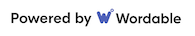
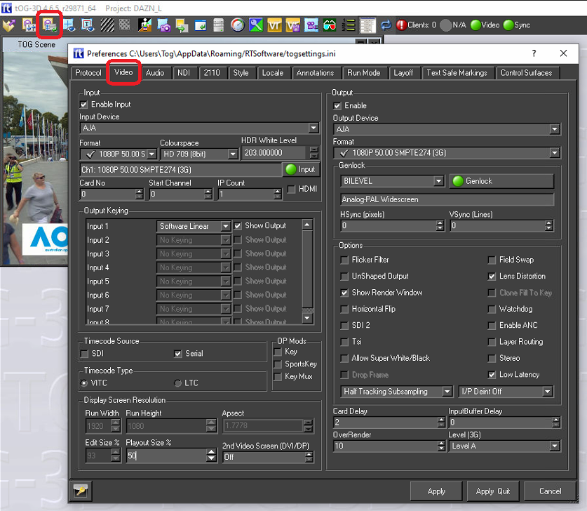
Video configuration is done from the “Video” tab in the “Preferences” menu:
Video Menu
The Video tab allows a user to specify the video devices in use, formats, size, filtering, keying etc for broadcast SD/HD video in and out. Note that depending on what you change, you will have to restart tOG for it to take effect (you will be prompted when this is the case).
Output
Changes in this section require a restart of tOG to take effect.
| Parameter | Description |
| Enable Output | Enable the Video output. |
| Enable Stereo | Enables Stereo Output |
| GPU Direct | |
| Output Device | Select the required output device |
| Format | Select the video output format. |
When a video output device is chosen, certain options will automatically be selected (these are the default values for the device) and some will be greyed out (these are not supported by the device).
Once a device has been selected the output format can be chosen from the drop down list. The formats with a tick next to them are supported by the chosen card and the ones with a red cross are not supported.
Genlock
There is also a drop down menu called GenLock (Generator lock) which can be used to select (if not grayed out) which device will be used for synchronisation. The options are INTERNAL, COMPOSITE and SDI. If you choose COMPOSITE, you MUST have an analog composite (back & burst) signal connected to the video cards ref-in connector. If you select SDI then tOG will lock to the video input signal. Note that in both cases, if no signal is present then the video will lock to an internally generated clock.
Output Options
Each format has a different default setting for the options shown, these will be greyed out unless a custom format is selected, in which case they can be adjusted manually to suit the user.
Under the heading control there are seven checkboxes which can be selected (as mentioned above these will be set to the default settings of the chosen video device) this may involve some of them being grayed out as they are not supported by the device.
The checkboxes which are not greyed out can be selected and unselected as required by the user.
| Parameter | Description |
| Flicker Filter | Applies a field based filter to the video out to reduce the effect of scan line aliasing |
| Unshaped Output | If checked, the fill will reflect the transparent states of graphics on the screen, and this will be reflected in the fill output. If the box is unchecked, Fill will only contain Fill information, and Key will contain all transparency information. The default is shaped output |
| Show Render Window | This will cause the render window to be displayed (or not) during Live mode |
| Horizontal Flip | |
| Field Swap | This will swap the field orientation when running interlaced video. This may be necessary in VR if you are keying over another source and the keyer cannot handle an odd field delay. |
| Lens Distortion | Enables Lens Distortion when tog is rendering through a VR tracking system. |
| Colour Bars | Displays colour bars through the SDI output. |
| Watchdog | |
| HSync (pixels) | Alter the horizontal genlock synchronization of the SDI video feed. |
| VSync (pixels) | Alter the vertical genlock synchronization of the SDI video feed. |
| Out Delay | Alter the output delay on the video card. |
| OverRender | When rendering with lens distortion, the video output will be distorted causing either a barrel distortion or pincushion distortion effect. Without overrender, gaps appear around the edge of the screen where there are no pixels to fill the distorted area. Overrender fills in the gaps left by this effect. The exact value to use varies based on the amount of lens distortion being applied by the lens that you are using. The value is specified as a percentage of the entire screen size. 10 is a good starting point. |
Input
This sets up the Video input for tOG. Usually this does not have to be selected since the system will automatically select the input based on your output setting. The only excep- tion to this is when you use the nVidia SDI card. In this case you need to setup the video in card separately
Enabling the keyer will cause the keyer on-board the video card to be enabled. This au- tomatically keys the graphics onto the incoming video input. NOTE: Do not use this key- er if you are reading in and using the internal chroma keyer.
As you choose each device certain options will automatically be selected (these are the default values for the device) and some will be grayed out (these are not supported by the device).
Once a device has been selected the output format can be chosen from the drop down list. The formats with a tick next to them are supported by the chosen card and the ones with a red cross are not supported.
Timecode Source
Choose the timecode source, used with the Sony 9 Pin Plugin.
- SDI – get timecode embedded into the SDI feed.
- Serial – get data embedded into the serial feed.
Timecode Type
Choose the type of timecode to use, when multiple are available.
- VITC – use VITC timecode
- LTC – use LTC timecode.
Output Keying
Choose the keying type used for each input channel.
| Key Type | Description |
| None | Tog does not key the video, only tog graphics will be output. |
| Chroma | Use the tog HSV chroma keyer |
| Segment | Use the tog segment keyer |
| Blue Matte Keyer | For use with Blue screen environments |
| Green Matte Keyer | For use with Green screen environments |
| Red Matte Keyer | For completeness, a red matte keyer is included. |
| Software Linear | Tog graphics linearly keyed over the top of the video input. |
| LAB Keyer | Use the tog LAB chroma Keyer. LAB is an alternative colour space to HSV. |
| Segment L Lab | Use the segment keyer using LAB rather than RGB colour space. |
Display Screen Resolution
If a video output is selected, this will determine the Run Width and Height. For all cards except Custom these values are fixed. In custom mode, the user can specify the Run Width and Height and aspect ratio.
| Parameter | Description |
| Run Width | The width of the output window |
| Run Height | The height of the output window |
| Aspect Ratio | The ratio of width to height of the run window |
| Edit Width | The width of the edit window, within the scene editor window |
| Edit Height | The height of the edit window, within the scene editor window |
| Playout Size % | This determines the size of the preview screen in Playout mode as a percentage of the render size. If the user is running HD then this should be at least 50% |
Tracking Configuration
The “Setup Files” page under the “VR Settings” tab on the “VR Interface” menu is used to select the tracker type and other files/values required.
Please note that these settings are project-dependent so before any of the VR Settings can be saved a project must be open in Swift Live. RTSW make available a small VR/AR test project called “SwiftOrigin”. If this is not already installed on your system please email “suport@rtsw.co.uk” and request the SwiftOrigin project.
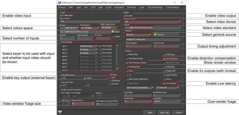
Swift projects are normally saved in folder DesktopRTSWprojects and each project has its own sub-folder inside folder projects.
To open a project in Swift Studio click on the “Open Project” icon top left. This will open a file browser. Navigate into the project, select the .prj file and click on “Open”:
When the project is opened the previously greyed-out icons at the top of the Swift windows become active.
Setup files
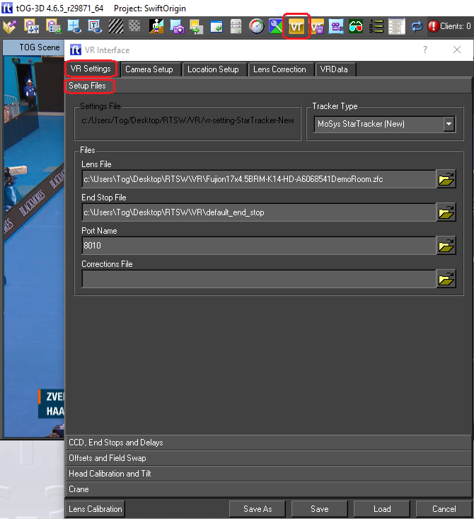
| Parameter | Description |
| Tracker Type | The type of tracking system being used |
| Lens File | The calibration file for the lens being used |
| End Stop File | A small text file used to store the end stop values of the zoom and focus encoders |
| Port name | The port name/number used to read the data – this should be set to the same value as the port number set in StarTracker. |
| Correction File | The file used to store lens calibration “corrections” when the lens calibration is “tweaked” |
Once all the parameters have been entered they can be saved to an existing “VR Settings” file by hitting the “Save” button. To enter a filename use the “Save As” button instead. All the files (the Lens file, the End Stop file and the VR Settings file) are conventionally stored in folder DesktopRTSWVR. When using “Save As” it is advised that a sensible filename is chosen – i.e. “VR-settings-StarTracker” so that it is obvious what the file is.
Tracker Setup
When StarTracker is first setup with Swift Studio there are various settings that need to be set correctly before the tracking will be correct.
Before adjusting these settings you must ensure that Swift Studio is setup for video and is receiving a clean video feed from the StarTracker camera. It is also convenient to be able to see the video output on a nice big monitor (24” or more).
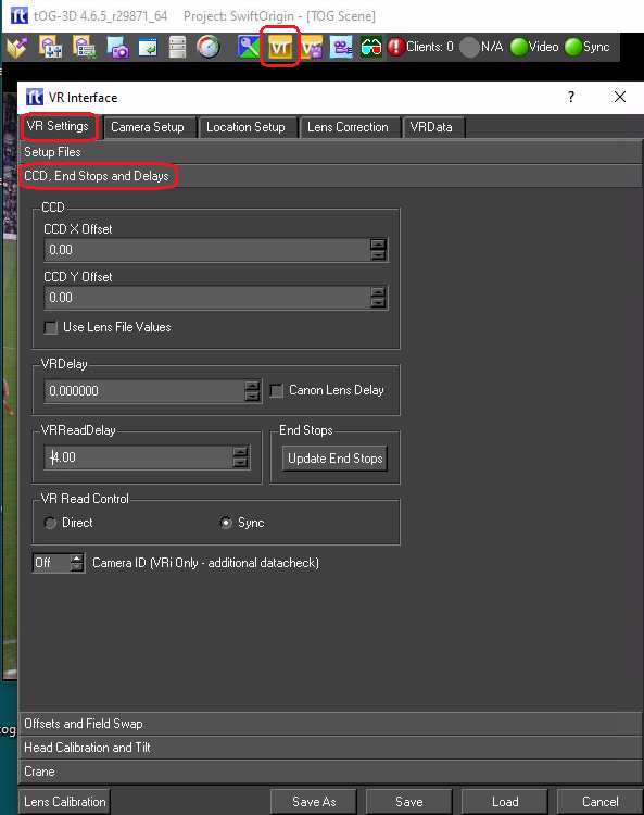
All of these settings are on the menu page “CCD, End Stops and Delays”:
CDD Offsets
The centre of zoom on a real studio camera is never exactly into the centre of the CCD array and hence the output video. The CCD Offsets is the difference, in X and Y, between the centre of the CCD array and the centre of zoom. Swift Studio needs to know these offsets to make the virtual camera match the real camera during a zoom.
The following procedure details the steps necessary to set the CCD offsets. This procedure needs to be done every time the lens is removed from the camera and then replaced on the camera. If the lens stays on the camera the CCD offsets will remain unchanged.
- Click on the CCD X Offset input box and small cyan cross-hairs should appear on the output. By panning and tilting the camera align the cyan cross-hairs with a well-defined real object in the studio. This should be done with the lens at full-zoom and the cross-hairs aligned with the real object as accurately as possible. The camera pan & tilt should be locked-off with the cross-hairs aligned and the lens at full zoom.
- Now zoom the lens to full wide being careful not to move the camera. The cross-hairs will no longer be exactly aligned with the real object.
- Adjust the CCD offsets in X & Y to re-align the cross-hairs with the real object.
- Repeat steps 1., 2. and 3. until no adjustment is required in Step 3. The CCD Offsets are now set correctly.
- As a final step click on Save (or “Save As”) to save the newly entered CCD Offsets into the VR Settings file.
VR Read Control
This parameter has 2 “radio” boxes – Direct and Sync. For StarTracker this setting should always be set to “Sync”.
VRReadDelay
This parameter should not be confused with the parameter “VRDelay” immediately above it on the menu.
The VRReadyDelay defines offset in milli-seconds from the genlock “start of frame” when Swift Studio will attempt to read the tracking data from StarTracker. StarTracker samples the encoders on the genlock and transmits the tracking data a millisecond or 2 later.. A value of -4 (as shown) is generally a good setting for the VRReadDelay. It tells Swift Studio to read the tracking data 4 milliseconds before the genlock – it will read the data that StarTracker sent on the previous genlock which will be saved in the tracking data input buffer.
Once set this parameter value should never need changing.
Update End Stop
The End Stop values are the encoder reading for the zoom and focus encoders at each end of their movement. Clicking on the “Update End Stops” allows the end stop to be read and saved. On-screen pop-ups give instructions for the 3 steps required:
- Run the lens zoom and focus through their full range. The zoom should be run backwards and forwards (full wide to full zoom and back) 10 times allowing a short pause at the end of each zoom-in/out. The focus should be run end-to-end at least 5 times. This first step ensures that StarTracker has picked up the full range of movement for each encoder.
- This is identical to Step 1. but in this step Swift Studio is reading the values sent by StarTracker and monitoring for the smallest and biggest value for each encoder. Again the zoom should be run full wide to full zoom and back again at least 10 times and the focus run over its complete range at least 5 times.
- Ensure the lens zoom is set to full wide and the focus set to infinity and click OK. This step informs Swift Studio of the encoders’ direction of counting and terminates the End Stop procedure. The End Stop values are saved in the End Stop file entered previously.
Once set this should never have to be done again.
VRDelay
Video from the camera is usually delayed with respect to the tracking data. The video has to be buffered into the PC and then cued into the graphics frame buffer, both of which cause a delay in the video whereas the tracking data is a direct connection and not delayed to the same extent. The VRDelay is a parameter, entered as frames, to delay the tracking data so that it aligns with the video data.
The delay can be seen by running a VR/AR graphic and then doing short, fast pan movements of the camera. If the graphic moves at the same time as the video the delay is correct. If the graphic starts to move first (or finishes moving last) then the tracking data is arriving before the video data and the VRDelay parameter should be increased slowly, delaying the tracking data, until the graphic and video move simultaneously.
With StarTracker this value is normally 0, 1 or 2 and should be set “by eye” as outlined above.
Once set this parameter should never have to be changed.
Correcting for Roll on StarTracker Data
The final step in the initial setup is to check for a roll offset in the StarTracker data. The tracking data sent by StarTracker includes the camera pan, tilt and roll. The StarTracker star-field calibration procedure does not and cannot check that there is no roll offset between the StarTracker upwards looking camera and the real studio camera and even a small roll offset will cause significant drift of the VR/AR graphics.
It is convenient to use the SwiftOrigin project to check the roll-offset and set any required offset. When run the project will render a checker-board pattern of white squares at studio floor level. Using the corner of a distant white square pan/tilt the camera until that corner is at centre-of-frame with the lens at full-wide, and lock off the camera tilt. Now position a real object on the studio floor so that it lines up with the corner of the white square.
Now pan the camera and look for up-down movement of the corner of the white square relative to the real object on the studio floor. If there is a roll offset in the tracking data the real object will go up (relative to the white square) when the camera is panned one way and go down if the camera is panned in the opposite direction.
The Camera roll offset (see screen-grab on next page) should be adjusted to minimise this up-down movement. The final value is normally very small – it should lie between about 2 and -2 degrees.
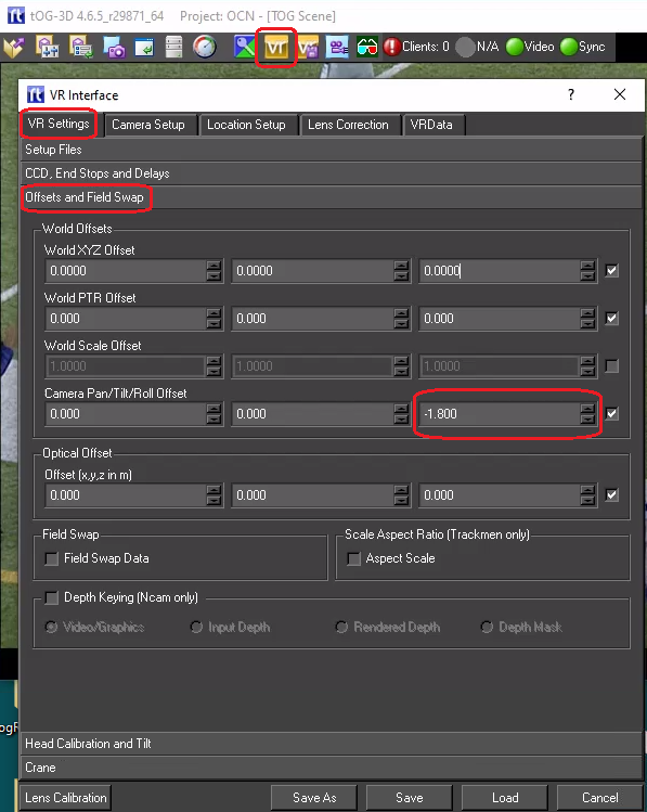
Once saved the Camera Roll Offset should not need to be adjusted unless the StarTracker upwards looking camera is removed and then replaced on the studio camera.
Complete System Testing
Once Swift Studio and the tracking data have been configured the system should be fully functional and ready to go. The most effective way of testing is to use a real project, preferably a project you will be using on-air. The graphics should be smooth and with negligible drift. If the output looks good and the illusion looks believable then you are ready to go.
Day-to-Day Operation and Troubleshooting
It is normal for a studio to be completely powered off when not in use. When StarTracker is re-powered it will automatically boot up and start outputting data. Following a restart and once StarTracker is running the only thing that needs to be done is to run the camera zoom and focus through their entire range several times. StarTracker is now ready for use. Start Swift Studio, load a project and all should be working fine.
Swift Studio Diagnostic Tools
Swift Studio has several tools to help diagnose problems:
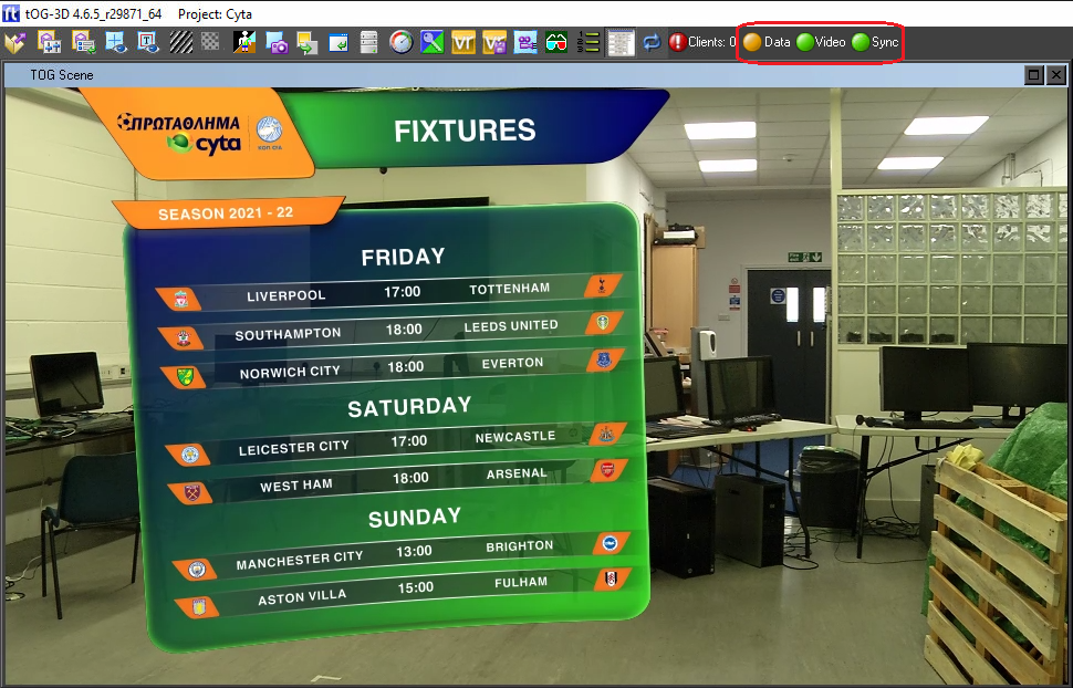
Tracking, Video and Sync LEDs
At the top right of the playout window there are 3 LED indicators:
| LED | Red | Yellow | Green |
| Data | No valid tracking data being received | Tracking data being received but it might not be genlocked | Tracking data being received and it is genlocked |
| Video | No input video present | Input video preset | |
| Sync | System is not genlocked | System is genlocked |
Tracking Data Values
The data being returned by StarTracker can be viewed:
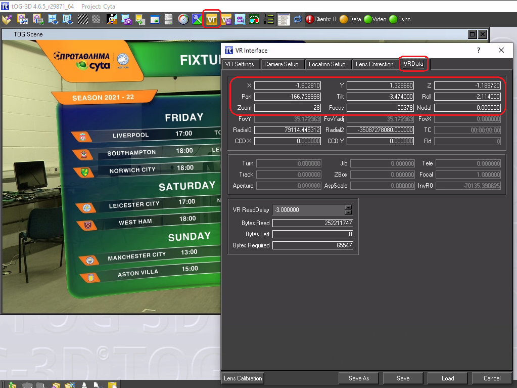
| Value | Quick sanity check |
| X, Y & Z | The current position of the camera. A quick check – the Y value should be the height of the camera above the studio floor. |
| Pan, Tilt & Roll | The current camera pan, tilt and roll. When the camera is level (horizontal) the tilt should be very close to zero. Tilting down should report a negative tilt. If the camera is panned to the left the pan value should get larger/less negative. Roll should never be larger than 2 or 3 degrees. |
| Zoom & focus | Values should change when the lens is zoomed/focussed |
Performance Data
Internal performance timings can be viewed:
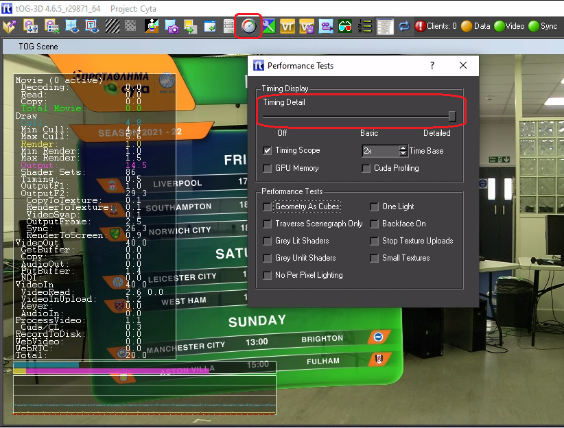
Sliding the “Timing Detail” to the far right brings up a column of timing data. The bottom value (Total) should be a constant 20ms (for 50Hz video) or 16.7ms (for 59.94Hz video). This is the total time taken to render a single frame (or field with interlaced video). If it exceeds 20 (or 16.7) then the system is not rendering in real time and the output will judder.
Log Files
Swift writes diagnostic data to a log file. The default location for the log file is:
C:Program Filestoglog
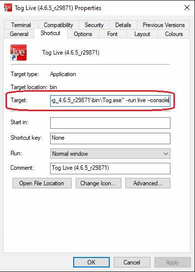
However, this may have been changed in the run icon. Right click on the icon and select “Properties” – then look for the “Target” line and look for an entry starting with –prefs like:
—prefs “C:userstogDesktopRTSWlogsSwiftARlogfile”
In the example below there is a “–console” argument. This will cause the text console window to stay open when Swift starts and debug messages can be seen immediately. This may cause Swift to drop out of real-time and is only recommended for debugging.
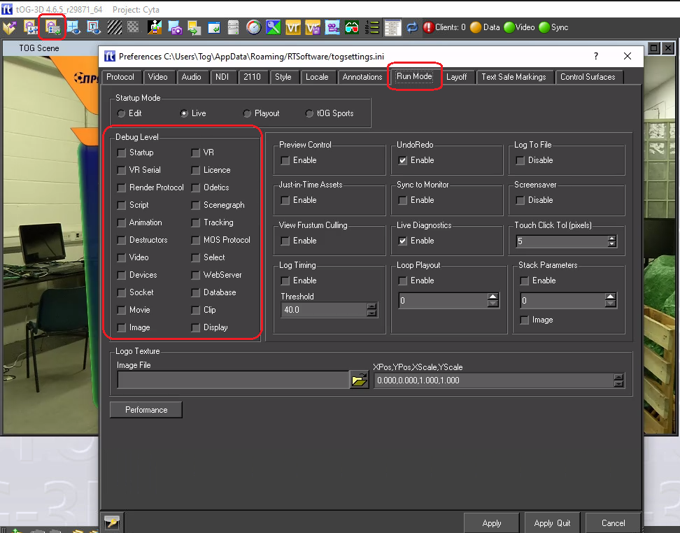
By default Swift writes useful start-up messages and errors to the log file. Increased debug data can be set from “Run Mode” in the Preferences menu:
Troubleshooting
Broadly speaking most problems fall into 1 of 3 categories:
- Video Problems
- Rendering Problems
- Tracking Data Problems
However, many symptoms are common across all 3 possibilities.
Video Problems
These problems include:
- The video input (i.e. the clean video from the studio camera) is missing (or black) or the video output is black.
- The video output is juddering
Video input/output missing or black
First check that no one has been fiddling with Swift and changed the video standard that Swift is expected to use. If Swift is expecting 1080i50 on the input and its being fed 1080p50 then it will show black on the input (and output). The video standard is checked from the “Video” TAB in the “Preferences” menu.
The next thing to check is that there is actually video coming into the PC. This can be checked using the AJA “cables” application which is normally left pinned to the icon bar.
If its not on the icon bar the application is:
“C:Program Filestogdriversaja16.2.0bincables.exe”
Run this application while Swift is also running.
When the application starts is will open a screen like this: (see next page)
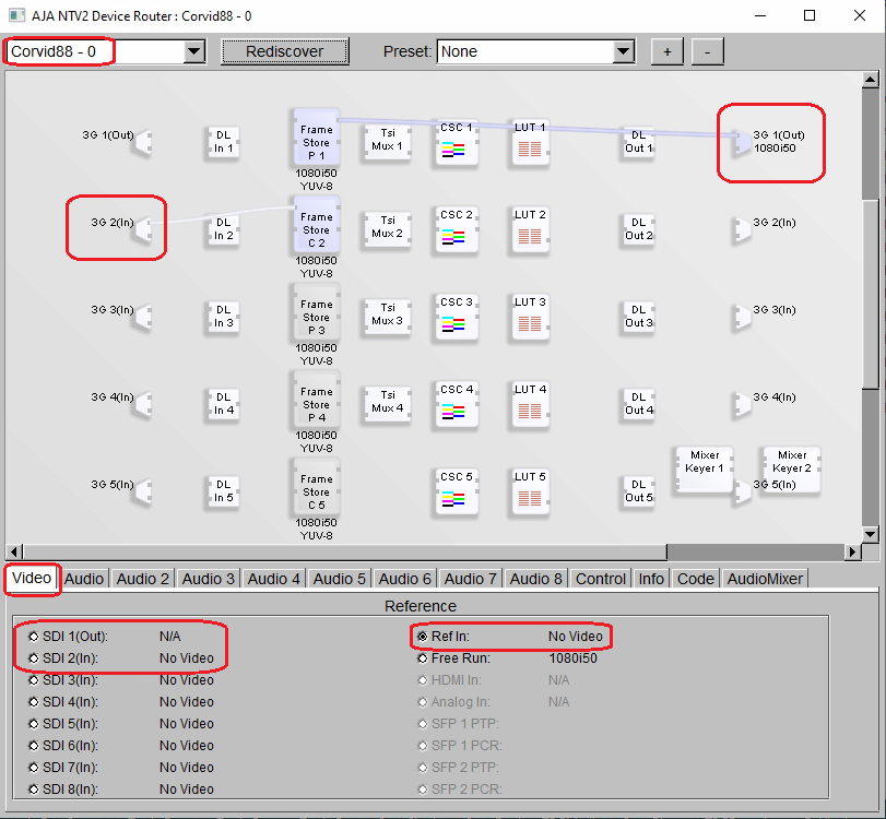
The above example is for an AJA Corvid-88 video card. The video inputs are shown down the left hand side and the video outputs on the right. The is 1080i50 video present on input 2 and 1080i50 video present on output 1. The blue (white) horizontal lines are the video routings setup by Swift. If they are blue then video is present on that route. show that. A white lines indicates no video present. In the above example Swift is using input 2 and outputting to output 1 and video is routed correctly in/out of the framebuffers.
Video input/output juddering
There are 3 likely scenarios:
- The video input is juddering on the PC monitor
- The video output is smooth on the PC monitor but on the SDI output video both the camera video and the graphics are juddering.
- The video output is smooth on the PC monitor but on the SDI output video the camera video is smooth but the graphics are juddering.
The video input is juddering on the PC monitor
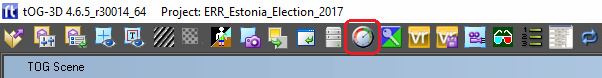
This likely indicates that Swift is not running in real time. This can be checked by turning on the timing data. The timing data menu can be found by clicking the “Performance Test” icon at the top of the Swift window:
See the section “Performance Data” above on how to check if Swift is running in real time.
The video output is smooth on the PC monitor but on the SDI output video both the camera video and the graphics are juddering.
Again this indicates that Swift is not running in real time.
See section above.
The video output is smooth on the PC monitor but on the SDI output video the camera video is smooth but the graphics are juddering.
In this case only the graphics are juddering and this indicates a problem with the tracking data. See section “Tracking Data Problems” below.
Rendering Problems
If the Swift project has recently been updated or a new project installed its possible that the project is now too complex/large to be rendered in real time.
Using section “Performance Data” above, check the render time. If the project is too complex/lage then the designers will need to modify the project until it does run in real time.
Tracking Data Problems
These will generally manifest themselves as the graphics not appearing (likely if no tracking data is being received) or the graphics juddering when the camera is moved. Check all cables are in place and StarTracker is turned on and shows OK on its own monitor. Most data problems are caused by a bad or missing genlock into StarTracker so check that everything is genlocked correctly.
Look in the log file for specific data messages (see section “Log Files” above on how to locate the log files).
In particular look for lines that include the words “Missed Message”. This indicates that Swift tried to read the tracking data but no data was present.
Check that StarTracker is running OK and that the ethernet connection to the StarTracker is present.
Occasionally, especially if StarTracker and the PC have been left running but unused for several days, the data connection will get corrupted. After checking for cable faults the best action is to reboot the StarTracker and the PC. The data should be stable after a full reboot of both systems.